There are many different ways you can edit home improvement videos. Here are some:
Make a Video From Photos
This is pretty simple to do. You can just add a bunch of photos to the video track of your video editor, animate each photo (many video editors can do this automatically), add some music to the music/audio track, and render the video. The result can be pretty good but it doesn’t really give a sense of the amount of effort or process involved. Here’s an example clip.
Regular 1x Speed Video
If you have a short video, leaving the speed at normal 1x speed might be okay. But, if your video is long, people will get bored very quickly. Since most home improvement projects take longer than 30 seconds, I don’t recommend this option, unless you are maybe adding a voiceover that explains what you are doing in the video.
Fast Speed (Timelapse) Video
Another option is to just timelapse the entire video. Some home improvement projects can take all day. Many people, including myself, will just leave a camera somewhere that will take many still photos at a set interval to create a timelapse video. You can also record an entire day’s worth of video, which I’ve also done using a WyzeCam mounted on a wall. Timelapsing an entire video is as easy as speeding up the video clip. The downside is the audio is also sped up and often doesn’t sound good so you usually mute the audio and optionally add some background music. Here’s an example.
Mixed-Speed Video
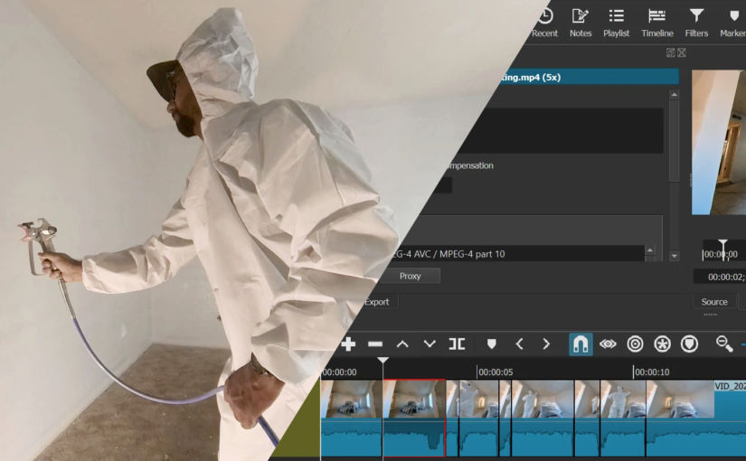
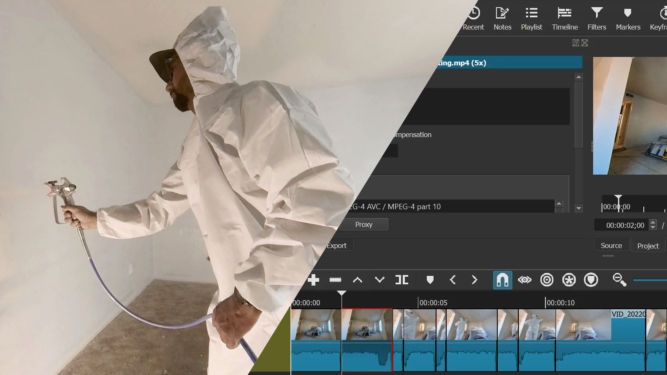
Another option is to timelapse (speed up) certain parts of the video and leave the other parts at regular 1x speed. This is definitely more work but I personally find this better than just speeding up the entire video. However, I find the best effect is when the regular speed segments are ones that have a high volume, e.g. when you’re using a tool that makes a lot of noise (drilling, jackhammering, cutting, etc). Here’s an example.
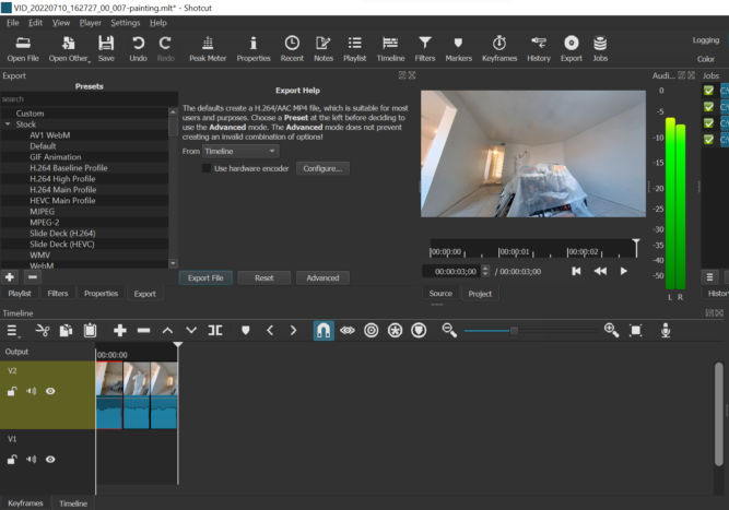
I normally use Corel VideoStudio to edit videos but for this purpose, I find Shotcut to be easier to use. Shotcut, which is free, shows the waveform very clearly, runs faster and hasn’t crashed on me yet. The UI takes some getting used to but once you get the hang of it, it’s pretty simple to us. Here are the steps I follow in Shotcut to create this type of video:
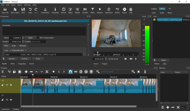
Open the original video in Shotcut
Drag it from the player to the timeline
Zoom in, if necessary, so that you can see the audio waveform
Choose some or all segments where the waveform is high (high volume)
Scrub the playhead until you find a segment where the waveform is high (high volume) and the segment is interesting to show at 1x speed
Split the video at that playhead position.
Move the playhead by where you want to end the segment. For 1x speed segments, I choose a duration of 1 second. You can advance the playhead by 1 second by going to “Player” > “Forward One Second”.
Delete any segments you don’t want to keep (choose Ripple Delete to remove empty space as well)
Click on a segment you want to speed up, click Properties, and change the speed. I choose 5x.
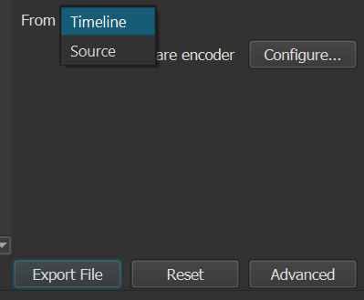
Click the Export button, select “Timeline” in the From field, and click “Export File”.
I changed the speed of this segment to 5x.
Video Showing Only Selection of 1-second Segments
Another option is to create a video from a selection of 1-second segments. Some segments will probably have high volume, e.g. drilling, jackhammering, cutting, etc. , Others may not, e.g. lifting, cleaning, drawing lines, etc. Again, I find this much easier to do in Shotcut than in Corel VideoStudio. Here’s an example.
Here’s how I do it in Shotcut:
Open the original video in Shotcut
Drag it from the player to the timeline
Zoom in, if necessary, so that you can see the audio waveform
Scrub the playhead until you find an interesting segment
Split the video at that position
Move the playhead forward or backward by 1 second (“Player” > “Forward One Second” or “Backward One Second”.)
Split the video again to create a one-second clip
Repeat steps 4-7
Delete all other segments (choose Ripple Delete to remove empty space as well)
Click the Export button, select “Timeline” in the From field, and click “Export File”
I reduced this 3-minute long video to 3 seconds (each segment is 1-second long) where the volume was high.
Merging Clips
If you end up with a bunch of video clips that you want to merge and you don’t need to apply any transitions or effects, you can merge them almost instantly with LosslessCut.
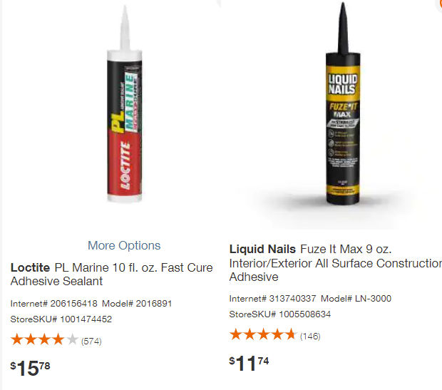
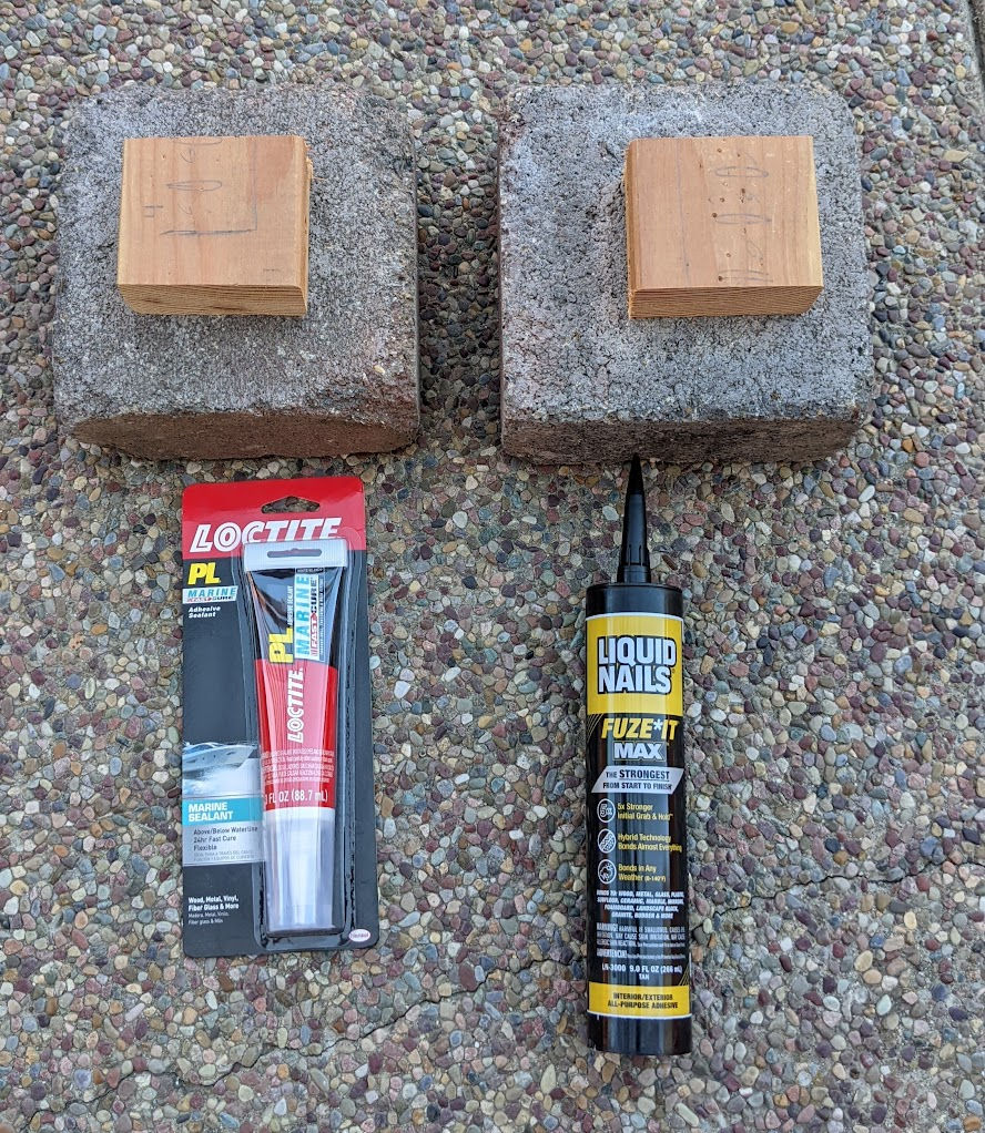
I wanted to find a glue that was simple to use, not too expensive, was very strong, and would maintain its strength in wet conditions. There are many glue options to choose from. I ended up choosing two popular brands: Liquid Nails and Loctite. For each brand, I chose either the strongest option or the option that was designed for wet environments. I didn’t include epoxy in my test because I didn’t want to mix two parts together and apply the mixture using a stick. Below are the two options I chose.
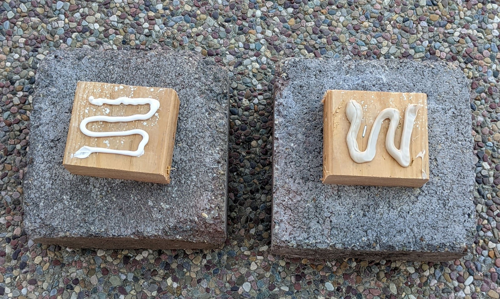
I first glued a piece of 2×4 to a concrete landscape block.
After waiting 1.5 to 2 days to fully cure, I attached each piece of wood to a chain to suspend the wood / concrete block combo in the air.
After 2 days, both adhesives kept the wood attached to the concrete block. I then wanted to see if water would affect the bond. I submerged each test in water without having it touch the bottom of the bucket of water.
LeftL Fuze-it | Right: PL Marine
After 12 hours, the wood pieces were still connected to the concrete blocks. But, after 23 hours, the Liquid Nails Fuze-It MAX lost its strength and the wood piece became disconnected from the concrete block.
Left: Fuze-It MAX, Right: PL Marine
So, the winner is Loctite PL Marine, although if you are gluing something in a dry environment, Liquid Nails Fuze-It MAX is probably sufficient. Unsurprisingly, the Marine adhesive is stronger both in dry and wet environments, including while being completely submerged in water.
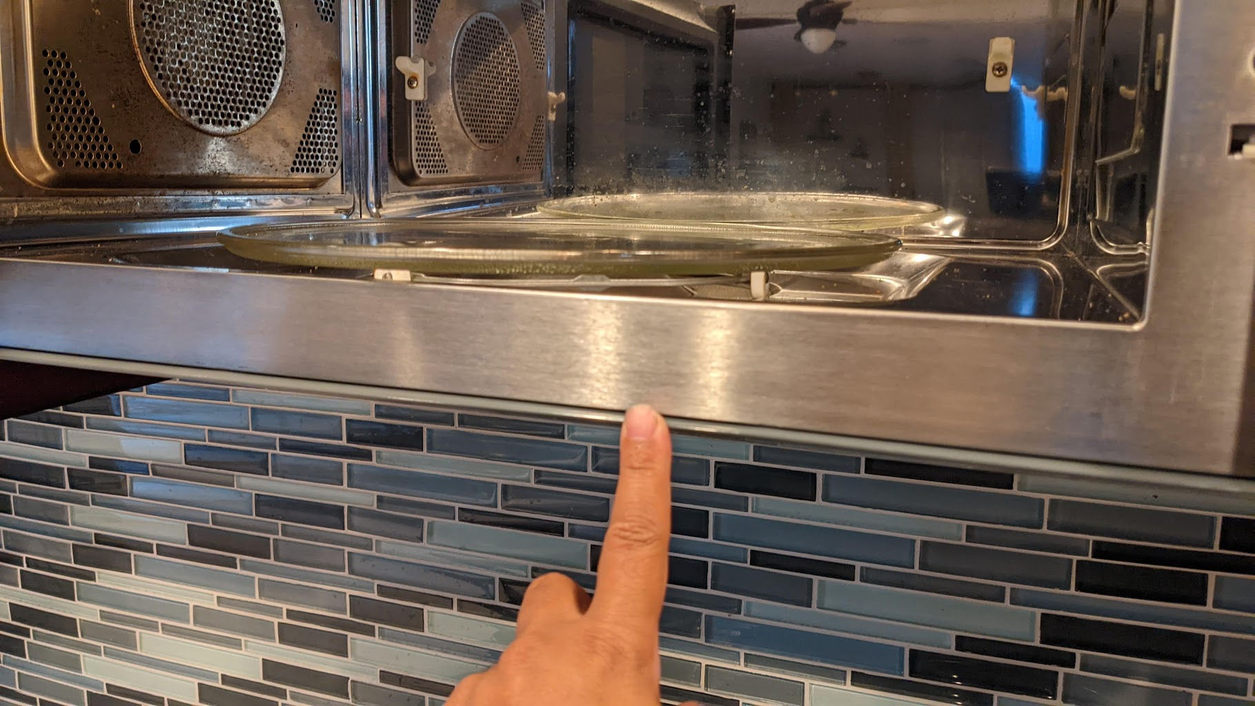
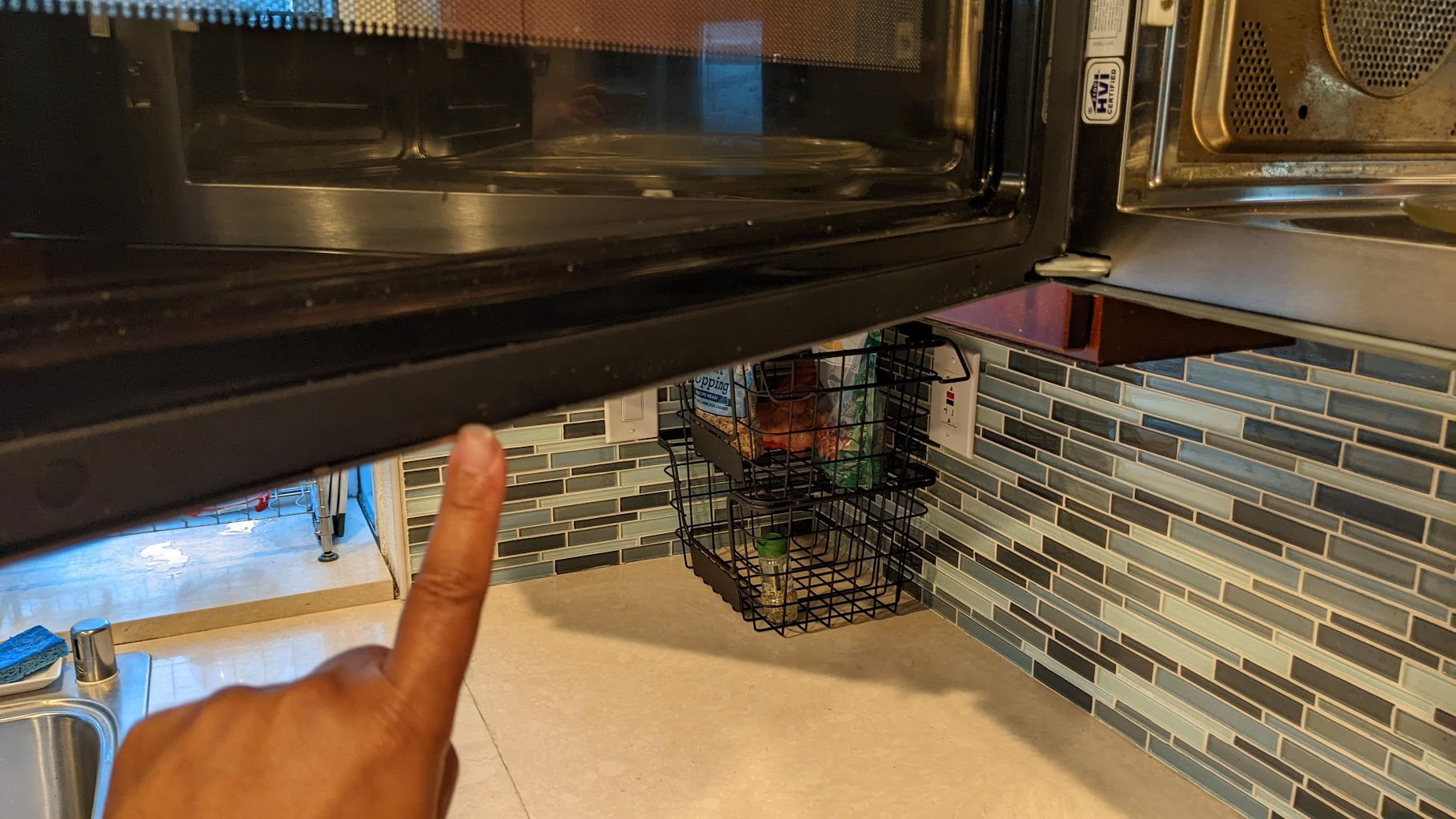
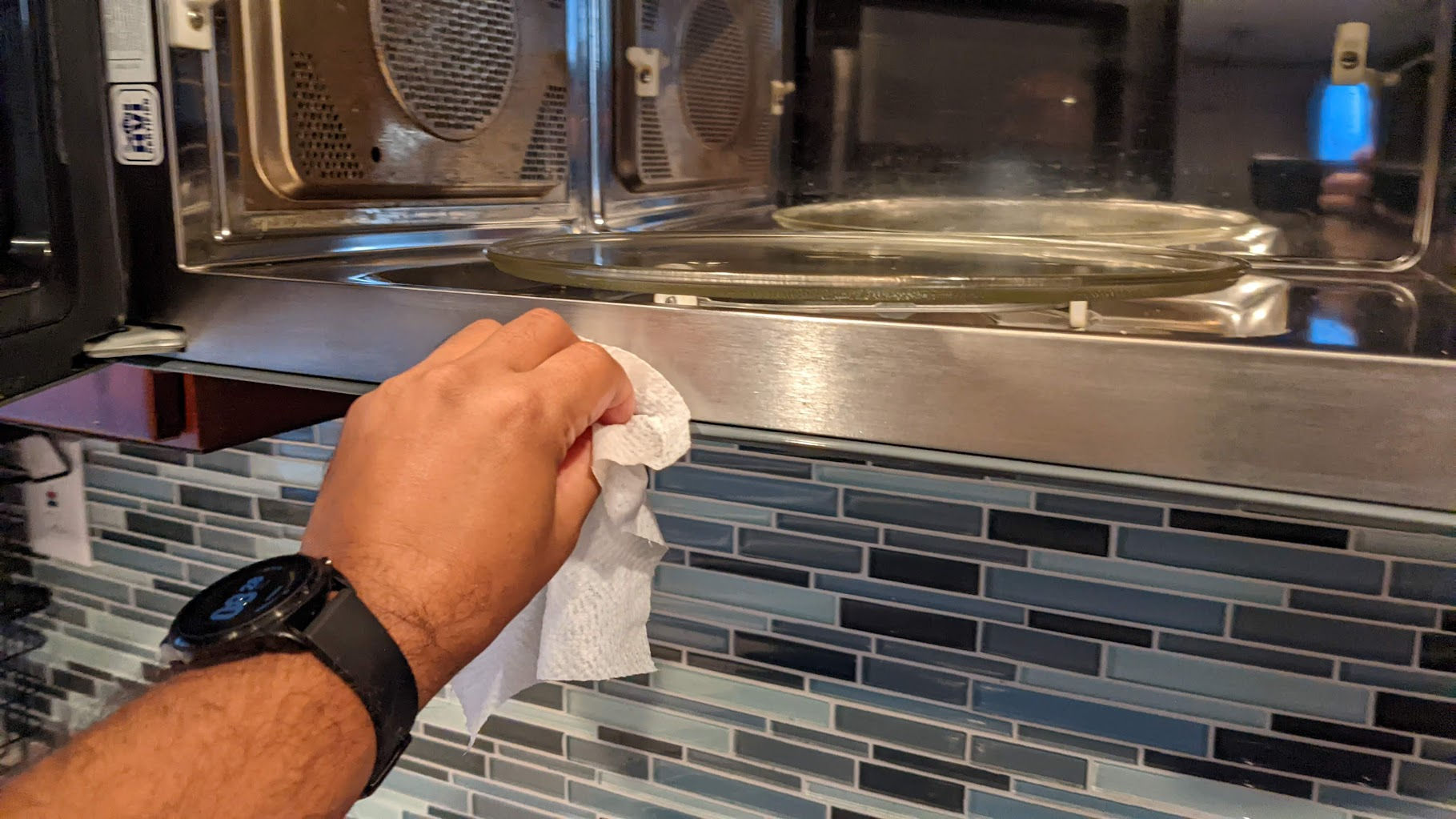
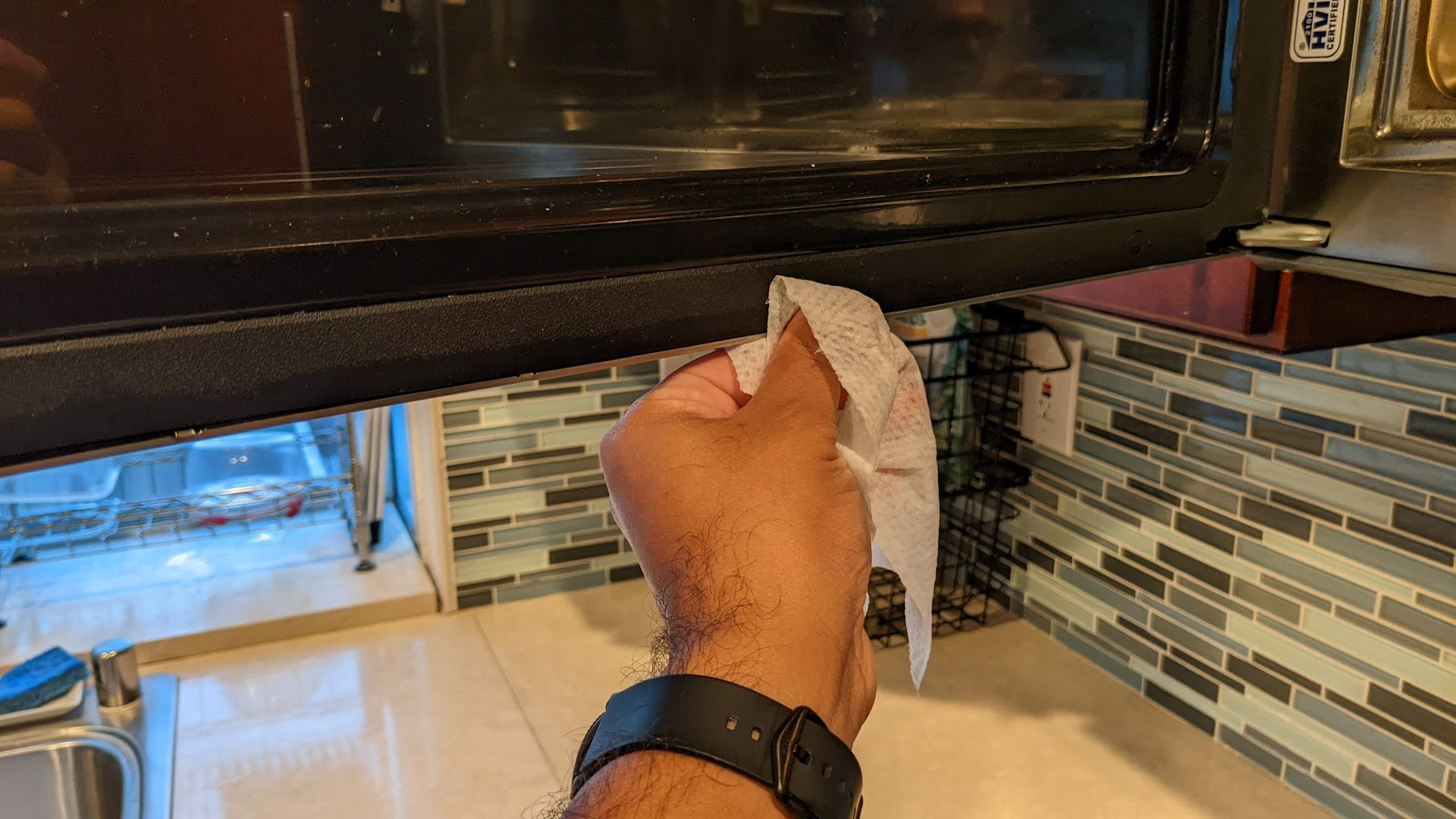
Recently, the microwave would keep giving an error saying I needed to “open / close door” no matter how many times I open and close the door. This prevented me from microwaving anything. Since this was an expensive microwave, I didn’t really want to buy a new one. Fortunately, fixing this error was easy. It turns out that there is a sensor along the inside front bottom edge that detects whether the door is closed or not. I prefer to clean using wet Clorox disinfectant wipes. I find that they lift dirt up easily. I’d then wipe again using a dry paper towel. After doing that, the open/close door error goes away and the microwave can start.
Door sensor along inside bottom edge of microwaveDoor sensor along inside bottom edge of microwave doorCleaning the door sensorCleaning the door sensor
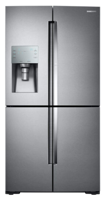
Do a Google search and you’ll find that many people have problems with the ice maker in their Samsung refrigerator. Of all the things Samsung can make, it’s ridiculous that they can’t even make an ice maker that just works without freezing up every 3 months. I have the 28 cu. ft. Food Showcase 4-Door Flex™ Refrigerator with FlexZone™ in Stainless Steel. I went with the counter-depth version. It’s smaller than the full-depth version but more expensive for some reason.
I have no problem with this fridge but as cool as it may look, the ice maker is a joke! I used up my extended warranty to have a “certified” technician come out 3 or 4 times to fix the ice maker (some of them are just clueless!). Anyway, in every situation, the ice maker stopped working because of ice buildup preventing the ice maker from working. One technician (a Samsung technician) said it was because I wasn’t using the original Samsung (overpriced) water filter. So, I put in an overpriced Samsung original water filter and, unsurprisingly, the ice maker still stopped working after a while – again, because of ice buildup. And, of course, I’m past the extended warranty so I have to fix it myself. If your stupid Samsung ice maker stops working because of ice buildup, here’s how you fix it (until it stops working again in 3-6 months).
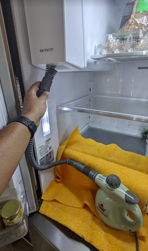
Buy a steam cleaner
I bought this Bissel steam cleaner on Amazon. It’s supposed to be used for cleaning but it works well for melting ice that jams your stupid Samsung ice maker.
Melt the ice
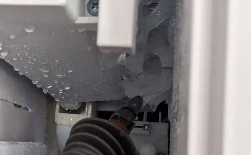
Put some water in the steamer, wait till it’s hot, then stick the nozzle up the ice maker opening and pull the trigger. Super hot steam will fill up the ice maker box and begin to melt any ice in there.
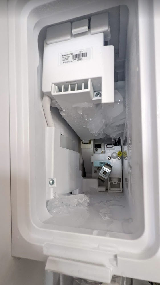
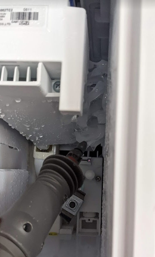
After a while, try to pull out the ice box. If it still doesn’t come out, repeat until it does. Once it comes out, you’ll see some ice buildup like in the picture below.
Use the steamer to target the ice buildup until you can remove all the ice.
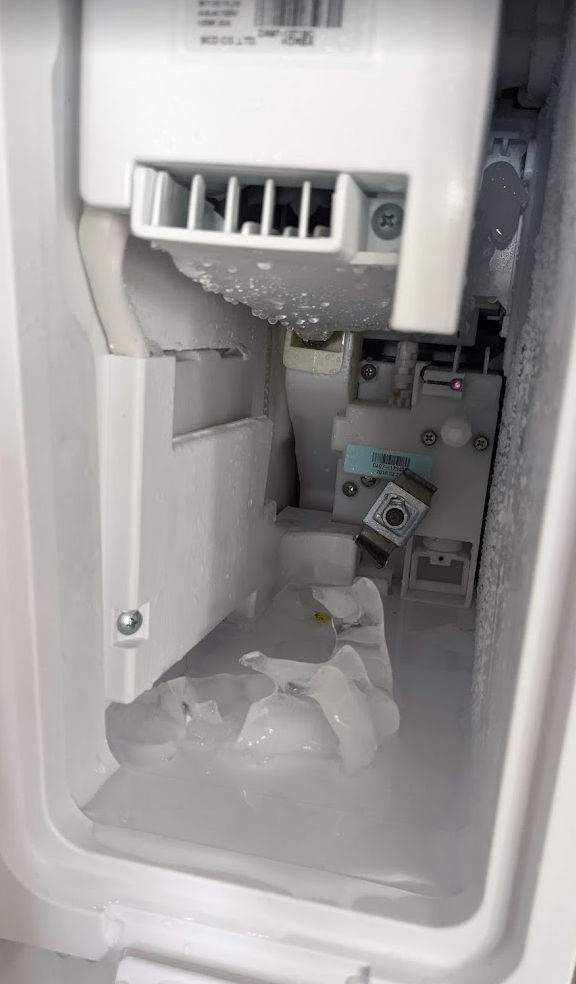
In the picture below, you can see that most of the ice is no longer stuck. Once you’ve removed all the ice, put the ice box back in and wait a day for new ice to be made.
And that’s how you temporarily fix your stupid Samsung ice maker.
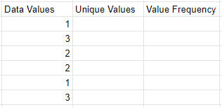
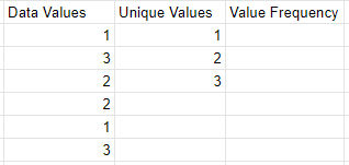
I’m often finding myself needing to calculate the frequency of unique values in a spreadsheet. It turns out it’s a 2-step process. For example, if you have a column of data as shown below and you want to know how many times the numbers 1, 2, and 3 occur, you need to first add a column containing the unique values in column 1. Then, you can use the frequency function to calculate frequency.
1. Get Unique Values
In column 2, get the unique values in column one using the unique function:
=UNIQUE(A2:A7)
If you want, you can also sort the values as follows.
=SORT(UNIQUE(A2:A7))
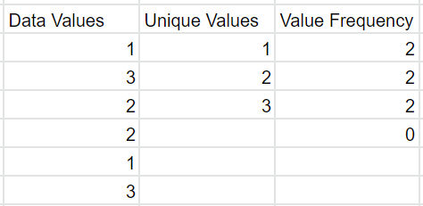
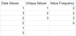
2. Get Value Frequency
In column 3, get the value frequency using the frequency function. The data is in column 1 and the classes are in column 2.
FREQUENCY(data, classes)
=FREQUENCY(A2:A7, B2:B4)
Google Sheets seems to want to add an extra row with the value 0. I just ignore that.
Note: the tutorial below works using Google Chrome and English subtitles where a user’s language setting in Netflix is set to English. It does not work for other languages like Arabic and Chinese. To download subtitles in those languages, you may need to change your language setting in Netflix.
1. Start playing a Netflix video
This tutorial uses Google Chrome.
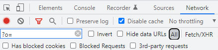
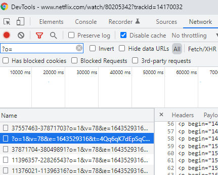
2. Open Chrome Inspector
Click CTRL+SHIFT+I to open the Google Chrome Inspector. Click the Network tab. Make sure “All” is selected. Enter “?o=” in the filter field. Make the video window smaller than full screen so you can see both the video window and the Inspector window side by side.
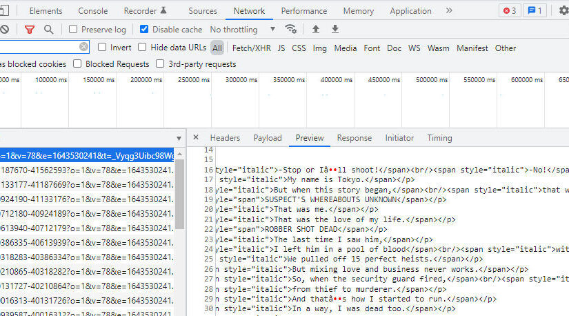
3. Find subtitle file
In the Inspector, sort the files by “Name”. If subtitles are turned on, you will see a filename that begins with “?o=”.
If you don’t see the file, then in the video, click to see the subtitle options and then click on a subtitle, e.g. “English”. You should then see the subtitle file appear in the list of files in the Inspector.
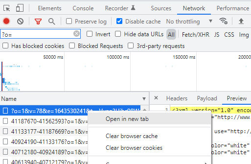
4. Download subtitle file
In the Inspector, right-click on the file and click “Open in a new tab” to download the file. Rename the file to something like english-subtitles.xml.
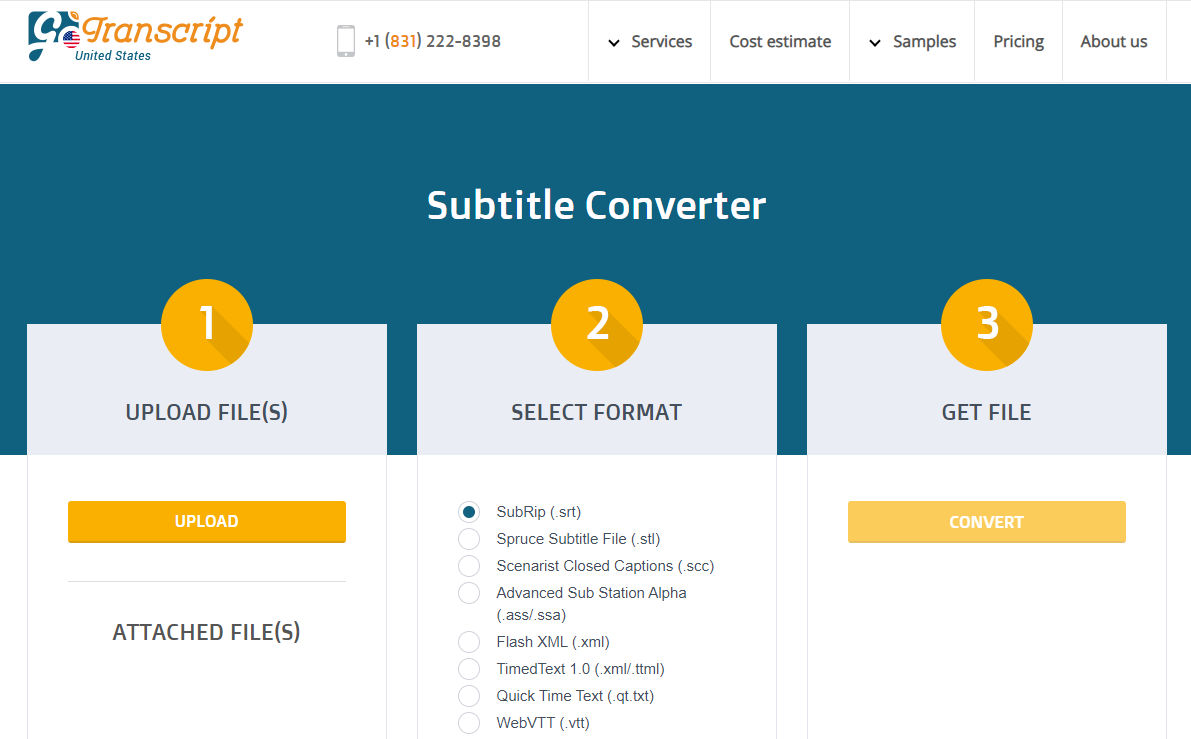
5. Convert subtitles to SRT format
The XML format of the subtitles may not be user-friendly. You can convert it to SRT format by going to https://gotranscript.com/subtitle-converter where you can convert the format for free.
If you have multiple subtitles, e.g. in different languages, you can merge them using this online tool.
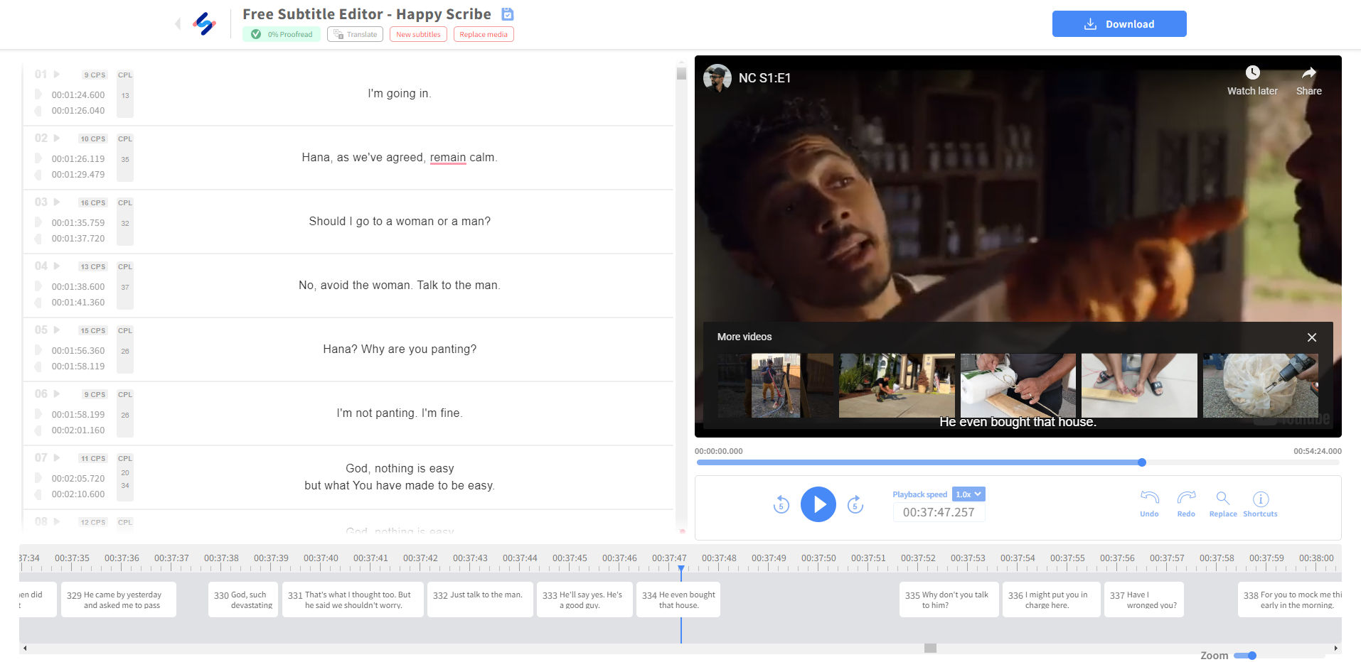
If you’d like to edit subtitles, you can try this free online editor. Some of the nice features are
clean user-friendly interface
can load a video from a YouTube URL
can change video playback speed
when you click on a subtitle, the video automatically jumps to the timestamp of that subtitle
When drawing rectangles, you can specify length & width by separating the measurements with a comma. For example: to draw a two foot by four foot rectangle, you can enter 2', 4' into the measurement box. The order of the measurements matches the order of the axes (R, G, B). For example: Red, then Green; Red, then Blue; or Green, then Blue.
When items are pre-selected, you can click anywhere in the model to begin moving them, and then click anywhere to set them down. This is an effective way to move things precisely and/or align things to other things.
Click the red crosshairs that appear on the bounding box of an object to rotate that object.
After moving a copy, you can type a number followed by the X key and then press Enter to create an array of copies.
Rotate, stretch, distort, or copy items or objects along a rounded path.
Tool Operation
(Optional) Preselect the items or objects you want to rotate.
Click on an item or object to both make a selection and set the center point of rotation.
Move cursor to indicate start point of rotation.
Click to set starting point of rotation.
Move cursor to indicate end point of rotation.
Click to complete rotation, or enter angle in degrees.
Modifier Keys
Ctrl = Toggle rotate a copy.
Before first click, hold Shift to lock protractor inference.
Before first click, use arrow keys to toggle the protractor inference lock direction (→ = Red, ← = Green, ↑ = Blue, ↓ = Parallel).
After first click, use arrow keys to toggle rotation inference lock direction (→ = Red, ← = Green, ↑ = Blue, ↓ = Parallel/Perpendicular).
Tips
Esc = Cancel operation.
During Step #2 of the tool operation steps above, you can click-drag the protractor along an edge or axis to set an axis of rotation.
After rotating a copy, you can type a number followed by the letter X and then press Enter to create a rotated array of copies.
When inputting rotation values into the Measurements box, you can enter either an angle of rotation, in degrees (for example 45 Enter),or a slope expressed as a rise:run architectural slope notation (for example 4:12 Enter).
(Optional) Preselect the items or objects you want to scale.
Click on a face or object.
Click on a Scale grip.
Move cursor to resize or stretch item or object.
Click to finish scaling item or object.
Modifier Keys
Ctrl = Toggle scale about center.
Shift = Toggle uniform scale.
Tips
Esc = Cancel operation.
Click a corner grip for 3-way scale. Default = Uniform. Pressing Shift = Non-uniform.
Click a midline grip for 2-way scale. Default = Non-uniform. Pressing Shift = Uniform.
Click a center grip for 1-way scale. Default = Non-uniform. Pressing Shift = Uniform.
When scaling an item or object you have the option to enter either a scale factor (for example 2.5 Enter will make the things you’re scaling 250%, or two and a half times bigger), or you can simply input the size that you want the thing you’re scaling to be (for example, if scaling up along the blue axis direction, 6' Enter will make the selection six feet tall).
It’s possible to activate multiple section planes at the same time, as long as the section planes are in different contexts. For example, you can activate one section plane through the model, and then activate another section plane through a group or component object and have both planes active at the same time.
Measure angles and create angled guide line entities.
Tool Operation
Place protractor’s center at vertex of angle.
Click to set vertex. (Alternatively: click and drag first point to set rotation plane.)
Move cursor in circle until touching start of angle.
Click to set start of angle.
Move cursor in circle until touching end of angle.
Click to measure angle.
Modifier Keys
Ctrl = Toggle create guide lines.
Before first click, hold Shift to lock protractor inference.
Before first click, use arrow keys to toggle the protractor inference lock direction (→ = Red, ← = Green, ↑ = Blue, ↓ = Parallel).
After first click, use arrow keys to toggle rotation inference lock direction (→ = Red, ← = Green, ↑ = Blue, ↓ = Parallel/Perpendicular).
Tips
Esc = Cancel operation.
When inputting rotation values into the Measurements box, you can enter either an angle of rotation, in degrees (for example 45 Enter ), or a slope expressed as a rise:run architectural slope notation (for example 4:12 Enter).
Click anywhere in the model to place the camera. The camera will be positioned above the point where you click, at the eye height distance specified in the measurements box.
(Optional) Click and drag from one point in the model to another point in the model to create a target camera. The point you drag from will be the exact location where the camera will be positioned, the point you drag to will establish the camera target.
Let’s say you want to make a closet in your garage and you want to create the frame using 2×4 lumber. It’s helpful to draw this in 3D to visualize the design. This post will show you how to do it using the free web version of SketchUp.
Set length units and precision
First, under Model Info, we set the length format and precision. Since a 2×4 piece of wood is actually 1.5″ x 3.5″, let’s set the length and precision to 1/2″.
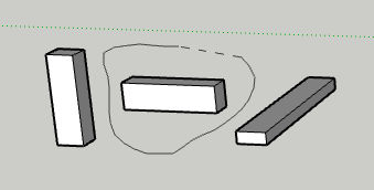
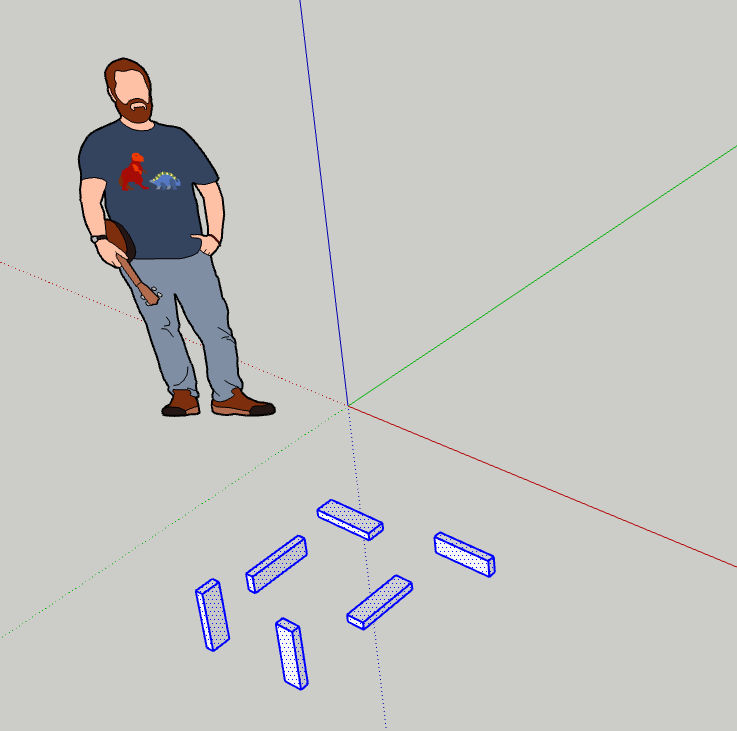
Create 2×4 objects that represent stock lumber
To simplify creating the closet frame out of 2x4s in 3D, we’ll first create 2×4 objects that are any length, e.g. 12 inches long, along each axis (x, y, and z). To do this, we’ll first create a 2×4 rectangle as follows:
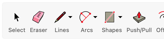
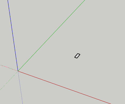
Choose the rectangle tool.
Click and drag anywhere until you see a rectangle.
Before clicking a second time, type “1.5,3.5” (without quotes) to manually specify the dimensions and then hit Enter. What you type will show up in the Dimensions field in the bottom right corner.
You will see the rectangle as shown below.
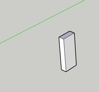
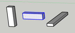
Now, we want to pull the rectangle to create a 12-inch long object representing a piece of wood. Click the Push / Pull tool.
Zoom in, if necessary. Then, click on the face of the rectangle and drag up. Do not click as doing so will set the length. Instead, type “12” (without quotes) to specify the length in inches to pull the rectangle to create a 12″ long 2×4. Then, hit Enter.
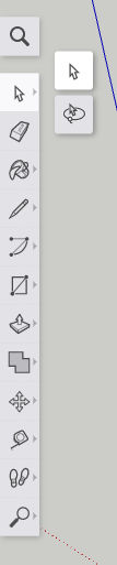
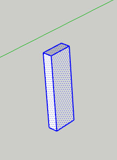
Now that we have one piece of 2×4 in one direction. Let’s copy and paste it twice to create two more pieces in the other two directions. Click the “Select” tool.
Drag a rectangle around the entire object you just created to select all of it. The object will turn blue as shown below.
Click Copy / Ctrl+C and then Paste / Ctrl+V to paste a clone of that object. Do this twice.
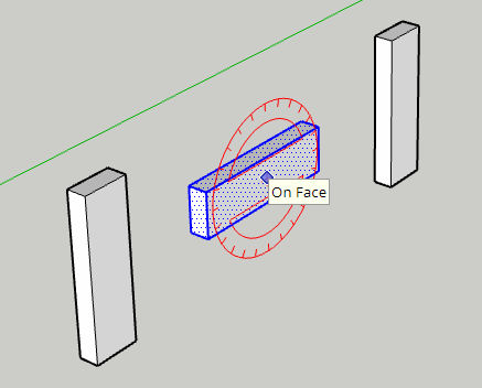
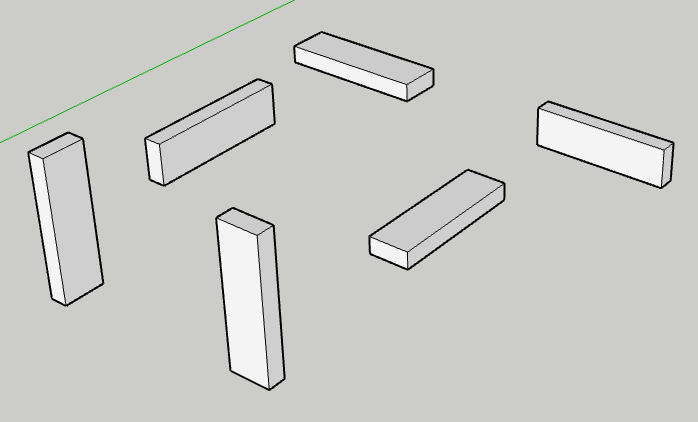
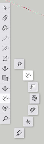
Now, select the 2nd object and then click the Rotate tool.
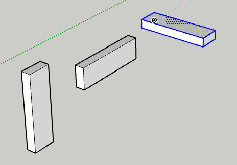
Click somewhere on the object and then click again to start rotating the object. Don’t click a third time since doing so would set the rotation angle. Instead, type “90” (without quotes) to rotate the object by 90 degrees.
Do the same with the 3rd copy of the object but rotate it in a different direction.
Come to think of it, we should make 3 more copies of the object and rotate them so we can have 2x4s in all 6 perpendicular directions. If you’re having a hard time selecting one entire object using the “Select” tool because it’s too close to another object, try using the “Lasso” selection tool.
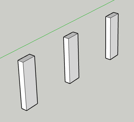
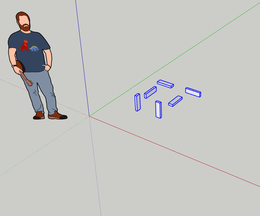
Now we’ve got our 2×4 building blocks which we can move to the side and clone to create the closet frame. I’ll select all 6 objects and move them as shown below.
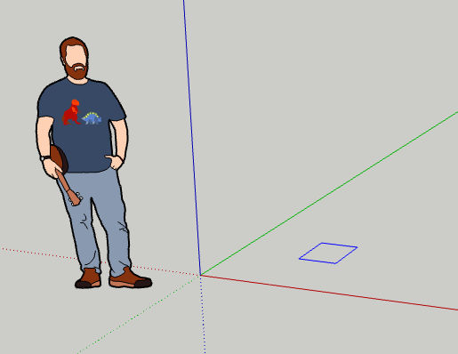
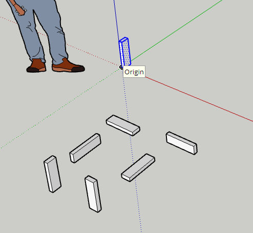
Now, we’ll create a closet frame by first cloning one of the building blocks, moving the clone, and pulling it to change its length. I’ll start with the back left corner of the closet frame. When I copied and pasted one of the 2×4 objects, I clicked on the origin to position the object there.
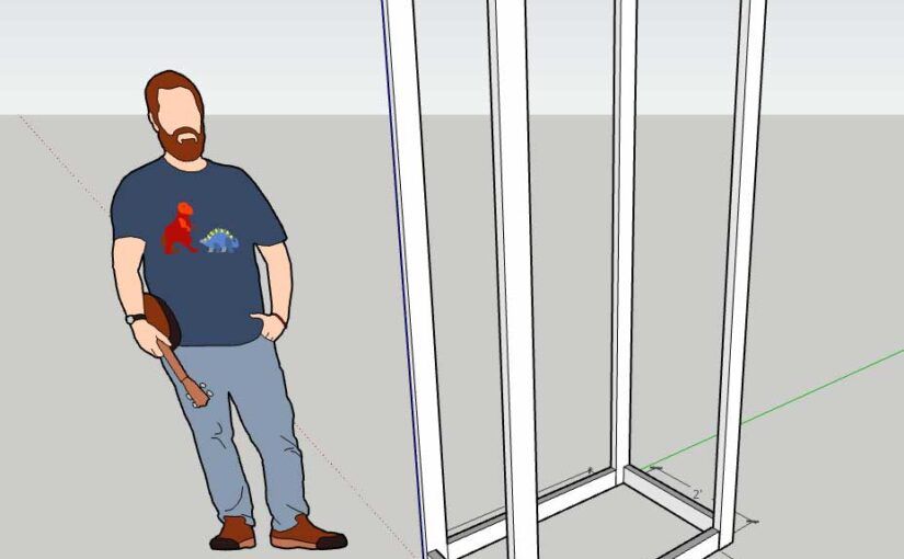
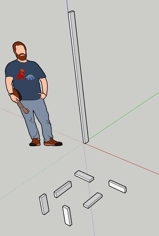
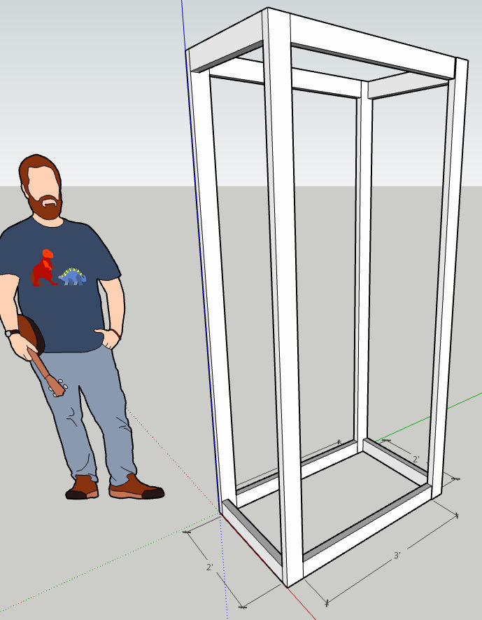
Let’s say we want our closet frame to be 80 inches tall. I’ll switch to the Push / Pull tool, click on the face of the object that I want to pull, drag up, and then type 80 to set the length to 80 inches.
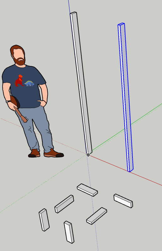
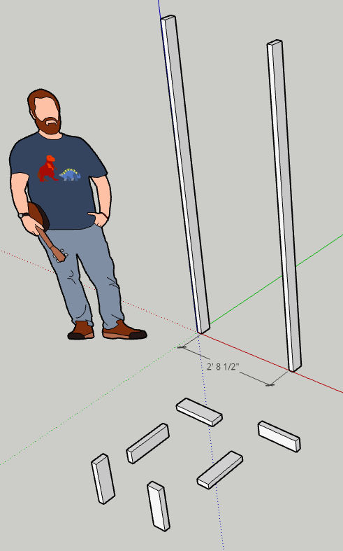
Since we want all corners to be 80 inches tall, we can clone the first 80-inch tall object three more times and position them as far as we want from each other. When you paste a copy of an object, you will see tooltips that help you align the object relative to the axes and to other objects.
Above, we see a copy of the 80-inch tall 2×4 but we don’t know how far it is from the first 80-inch 2×4. Click the Dimensions tool.
Then, click on each of the two endpoints of the distance you want to measure. In this example, the distance is 2′ 8.5″.
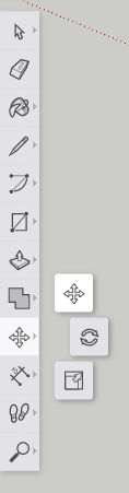
Let’s select the 2nd object and then click the Move tool so we can move the object to be 2 feet away from the other object.
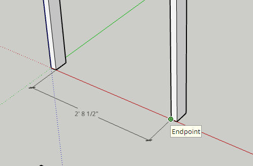
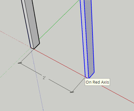
Click on one corner / endpoint and then drag such that the distance becomes 2 feet.
When dragging, you’ll see tips such as “On Red Axis” which will help you stay on the same plane and only move in one direction. Below, we now see the distance between both objects is 2 feet.
Repeat the above steps for the remaining parts.
To learn more, including how to move and align objects relatively and absolutely, read my other SketchUp article.
So, last week I renovated one of my rental properties. This included replacing an old kitchen from 1995 with a new one. Here’s an overview of the process.
1. Take a picture of and measure the old kitchen cabinets
I just drew the measurements in Photoshop. Note that the picture below is what the cabinets looked like in 2008. The remodel was done in 2021 and the cabinets were is much worse condition then.
2. Design and order new cabinets
Cabinet Prices
Cabinet prices can vary widely. Home Depot, for example, is expensive. HD Supply has cheap cabinets but they look cheap. IKEA’s cabinets are mid-priced but you have assemble them. Chinese stores have cheap cabinets that look expensive. They also come pre-assembled. But, you have to inspect each cabinet before installing them because their quality control isn’t very good.
Cabinet or Drawers
There are base cabinets that sit on the floor and wall cabinets that are on the wall. Wall cabinets are always just cabinets with a swing out door. They are more expensive if the door has a glass window in it. Base cabinets can be regular cabinets or have drawers. If they are just cabinets, then you’d have a hard time reaching for items in the back of them. If they are drawers, then you can just slide out the drawers to access anything in them. Since drawers require more material and come with sliding mechanisms, they are more expensive then drawers.
Types of Cabinets
2D / 3D Design
I ended up just buying the cabinets from a Chinese store (warehouse) called Uni Tile & Marble.
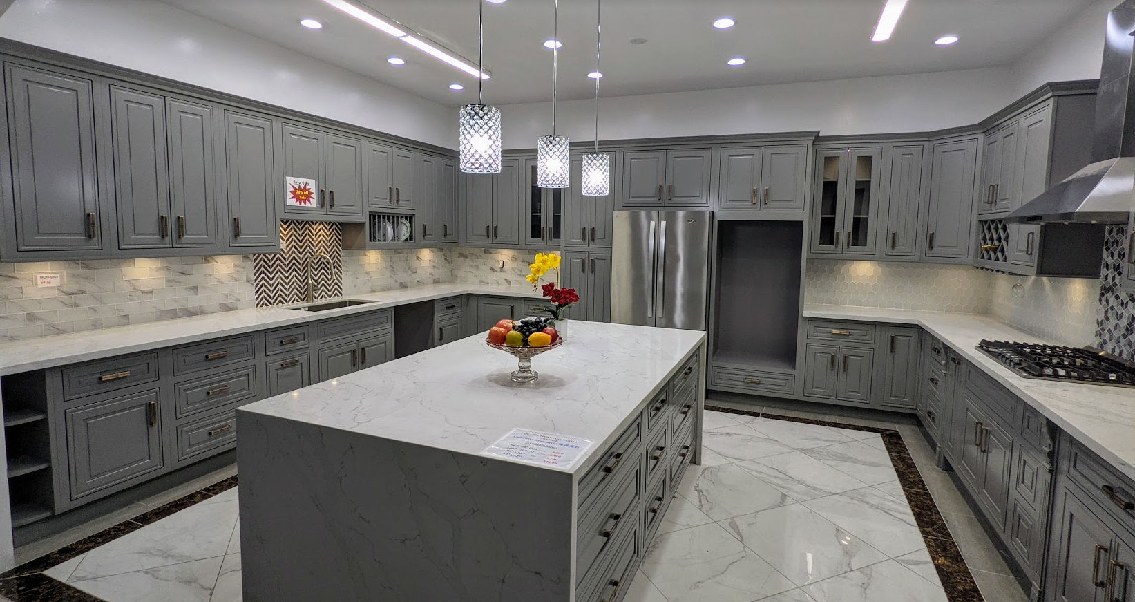
I ended up choosing solid gray color cabinets. This is because the house is a rental house and tenants somehow ruin the surface of the cabinets, I can later just easily repaint the cabinets. This is what the cabinets look like in the showroom.
Countertops
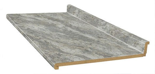
For the countertop, the one on display was off white with a random gray design.
It contrasted well with the gray cabinets and looked exotic but it was also more expensive than other countertops on offer. I decided to go with a cheaper countertop ($300 per 8 foot slab) but my tenant offered to pay the difference for the more expensive countertop so I ended up getting the more expensive one.
Quarts countertops are super heavy and require special handling and are not easy to cut. I ended up paying the store to transport and install the countertops. If you’re looking for a cheaper DIY option, you can just buy cheap laminate countertops at the Home Depot and use a simple jigsaw to cut out the sink hole.
Sinks
For the sink, I prefer the large single basin type. Even though they’re available at Chinese stores, Chinese stores then to have outdated return policies with unreasonable restocking fees (25%) so for these types of items, I buy them at the Home Depot or Lowes.
Faucet
For the faucet, I definitely prefer the type in the picture below. It makes it easier to spray and clean the entire sink or whatever else you are washing / cleaning.
3. Pick Up New Cabinets
I could have had the cabinets delivered for a ridiculous $200 fee but since I need to dispose of the old cabinets, I decided to rent a 10′ U-Haul box truck to both pick up the new cabinets and transport the old cabinets to the dump.
A 10′ box truck was big enough to lay all cabinets on the truck bed.
The house were the cabinets will be installed.
4. Demolish Old Cabinets
The old cabinets were original to the house from 1995. They were definitely low quality cabinets. They were just screwed into the wall. Some sections were large so I used a Milwaukee Monster sawzall to cut cabinets in half.
5. Dispose of Old Cabinets
Since we had the truck for 24 hours, we loaded the old cabinets and other construction debris in it
and took it to the dump where I paid $138 to dump it all.
6. Prepare Wall
After removing the kitchen cabinets, the walls needed to be patched up and painted.
First, we enlarged some of the holes in the wall by cutting with an oscillating tool. The holes were shaped like rectangles where vertical edges would be along the center of studs. This would allow us to screw drywall nails through them into the studs. Cutting drywall was easy using a small, cordless reciprocating saw.
We then patched crevices with spackling paste.
After waiting for the spackling paste to dry, I then used an orbital sander to smoothen the wall surface.
I then sprayed wall texture to try to match the texture of the existing wall. This didn’t work well as the material was often clogging up. Next time, just use an air compressor with an actual texture sprayer gun.
I then painted the ceiling Swiss Coffee.
And painted the walls Roman Plaster.
I then touched up the corners where the two colors met. Semigloss paint was used to make cleaning easier.
7. Mark Walls
After the paint dried, we marked where all the studs in the wall were using a stud finder and then marked level (horizontal) and plumb (vertical) points using a laser level.
Then, we connected the points and drew outlines for where the cabinets would go. Note that the distance between the countertop to the bottom of the wall cabinets should be 18 inches.
8. Install Cabinets
We then installed the wall cabinets first. To facilitate this, we screwed a 2×4 to the wall so we could sit the cabinets on it while we screw the cabinets into the wall. If a cabinet didn’t span 2 studs, we’d use drywall anchors.
If walls or floor are not level or flat, use shims.
9. Install Cabinet Handles
To facilitate installing the cabinet handles perfectly, we bought a plastic template / jig. It did not work for drawers, though, so for drawers, we made our own jig.
10. Install Microwave
Since the microwave goes above the range, we installed that next. This required cutting holes in the cabinet above it for bolts and the vent.
11. Install Plywood on Base Cabinets
We then cut plywood and screwed it to the base cabinets.
12. Install Sink
We then cut a hole in the plywood for the sink using a mini circular saw for the straight sides and a jig saw for the corners. Then we installed the faucet, soap dispenser, dishwasher air gap, and garbage disposer to the sink and then installed the sink. This was done before installing the countertop because the countertop would not be ready for another 2 weeks.
I just got a top mount sink that includes the faucet holes rather than an undermount sink. This simplified installation.
13. Install Crown Molding
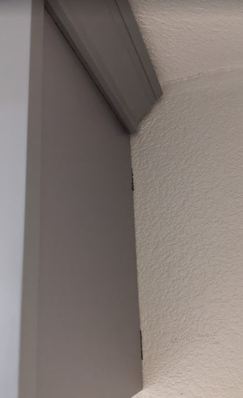
We then installed the crown molding. This was very tricky for a couple of reasons.
depending on the shape of the top of your wall cabinets and the shape of your crown molding, there may not be enough surface area to shoot finish nails into or there may not be enough clearance to shoot nails from above
cutting miter angles can be tricky and holding the crown molding down on the miter saw the same way isn’t easy.
Cutting the crown molding
Fortunately for this project, we only needed 45 degree cuts. But, we messed up a few times at first and wasted some expensive molding. Here are some tips to cut crown molding easily and correctly each time.
Label the surface of the miter saw “TOP” to remind yourself that the top of the crown molding should be facing down and the bottom of the molding flat against the fence.
Find a way to secure 2 pieces of wood to the sides of the miter saw.
Place your crown molding against the fence and then screw a piece of plywood or wood board to the two pieces of wood on each side of the miter saw. This allow you to put the crown molding on the saw at the same angle every time ensuring perfect cuts.
Installing the crown molding
For our particular case, we decided to secure the crown molding to thin plywood using small screws. We then lifted it and let it sit on top of the wall cabinets – no further screwing or nailing necessary.
14. Install Baseboard and Trim Molding
We then cut the baseboard and trim molding to length and shot them into the cabinets using a finish nailer powered by an air compressor. The baseboard and molding were necessary to hide gaps between the cabinets and the floor and walls.
15. Install The Countertop
For the countertops, I decided to go with quartz instead of marble. Since it’s very heavy and tricky to cut and to smoothen the edges, I decided to just pay someone to install the countertops.
First, one of the 8 foot slabs was cut to go on each side of the range. I believe this was done using a diamond blade.
A thin strip of the excess material was cut to make a finished end. The strip was secured using a special epoxy glue.
The strip was then clamped down and the epoxy left to cure for a while.
The installer intentionally cut the slab and the thin strip to be longer than the final length so that after the strip was secured he could cut and trim the end where you see all the glue oozing out.
This resulted in a very clean joint. He then smoothened the end.
This is how the joint ended up looking (with some dust that would eventually be wiped off).
For the sink side, a hole was cut out.
To create rounded corners, the installer cut a bunch of lines at each corner.
And then using a flathead screwdriver, broke off the thin pieces.
And then used an angle grinder to grind away rough edges to create a smooth rounded corner.
They then glued the quartz countertop to the plywood.
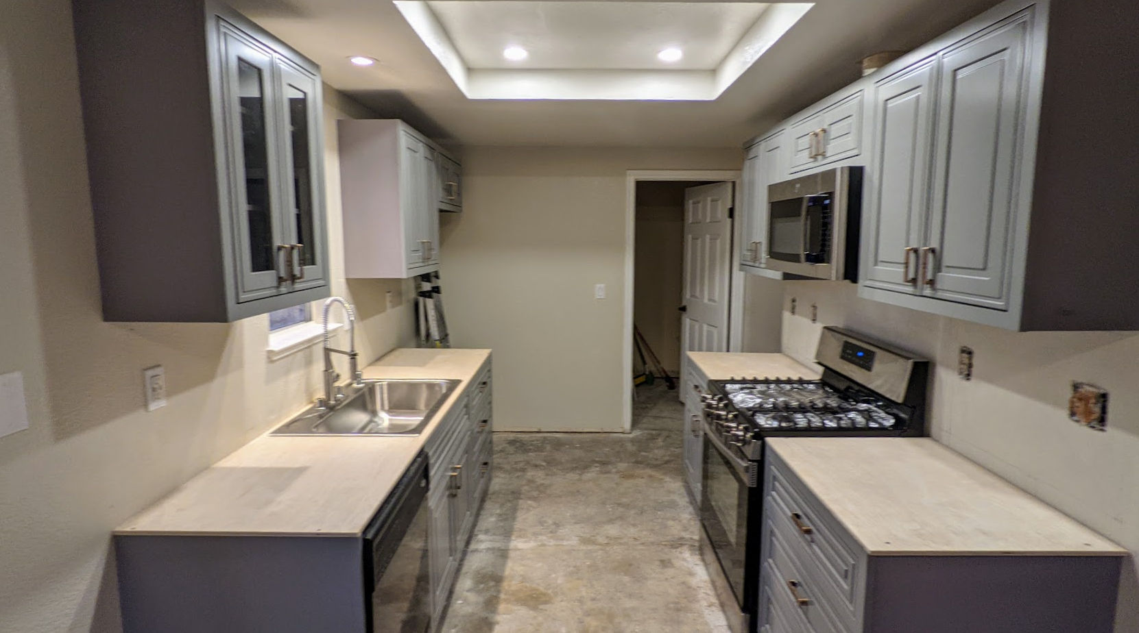
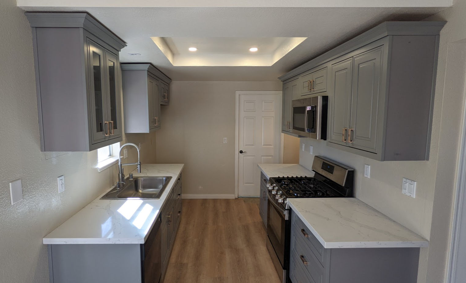
And this is the end result.
Note that we also
replaced the flourescent tube light box with flat LED lights
painted the walls BEHR Roman Plaster (semigloss)
replaced the old style kitchen outlets and switches with new Decora ones including adding a dimmer for the very bright LED lights
replaced the linoleum sheet / vinyl tile flooring with LifeProof Dusk Cherry luxury vinyl planks.
Tools
This project was big enough that I ended up bringing most of my tools to the worksite.