


If you have an electrical outlet or switch that isn’t working, here are some steps for debugging and fixing the issue. First of all, it’s important to understand the flow of electricity within a typical home.
Electrical Components and Electricity Flow
- Electricity comes through a cable from your local utility to your house
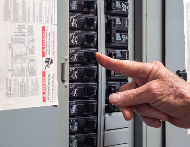
- That cable enters a circuit breaker panel on a wall
- The circuit breaker panel contains many circuit breakers.
- Each circuit breaker has electrical wiring to different parts of the house (kitchen, bedrooms, living room, bathroom, garage, etc). For example, below is a picture of electrical wiring from one circuit breaker in the panel going to 4 outlets. The wiring (or circuit) forms a loop. Electricity flows
- from the panel
- through the circuit breaker
- through the black (hot) wire
- through each outlet
- through the white (neutral / return) wire
- through each outlet
- and back to the circuit breaker panel
The bare copper or green wire (ground) goes from each outlet to the circuit breaker panel and then to a rod stuck in the ground.

- Each circuit delivers 120 V (volts) of electricity or 240 V depending on the use. Most circuits carry 120 V but electric ranges, electric water heaters and electric clothes dryers carry 240 V since they require more power to function.
- Each circuit breaker is rated for a specific number of amperes (amps). Usually 20 A for circuits that require more power, e.g. kitchens, and 15 A for circuits that don’t require much power, e.g. bedrooms.
- Circuits that require more power (e.g. 20 Amps vs 15 Amps) use thicker electrical wiring. The smaller the gauge number, the thicker the wire.
- 12 gauge Romex is rated for 20 Amps and is commonly yellow jacketed.
- 14 gauge Romex is still used in some applications and is rated for 15 Amps and is grey jacketed.
- 10 gauge Romex has an orange jacket and is used for water heaters or clothes driers.
- The power (P) available to any particular circuit is determined by the voltage (V) running through it and the amps (A) the circuit breaker and the wiring support. The formula for power is P = VxI. So, if a circuit has 120 V and is rated for 15 A, then it supports a maximum power of 120 x 15 = 1800 Watts.
- Each device (toaster, laptop, lamp, refrigerator, TV, etc) plugged into an outlet or is in a circuit draws power. The device will indicate how many amps it draws or power (in watts) is consumes to work. For example, below is a label on the back of a toaster oven. It requires 120V AC (alternating current, as opposed to DC, direct current) and it consumes up to 1200 W of power.

This toaster, which consumes up to 1200 W, can be used on a 15 A circuit because a 15 A circuit supports up to 1800 W of power. However, if two of these toasters were plugged in to the came 15 A circuit, then they’d both consume up to 1200 + 1200 = 2400 W which exceeds the power rating of the circuit. This would cause the circuit breaker associated with the circuit to trip and disconnect power to the circuit. Without the circuit breaker, the 15 A rated wiring would begin to melt due to the heat buildup and possibly catch on fire. If the circuit breaker turns off, you can toggle it back on.
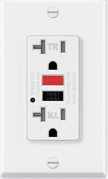
In the picture above, the first outlet is a GFCI (ground fault circuit interrupter) outlet. It behaves like a circuit breaker. If the total power drawn through the outlet exceeds its rating, e.g. 15 A or 20 A, then the outlet would disconnect itself from the circuit thereby rendering the entire circuit without power because it is the first device in the circuit. If a GFCI outlet turns off, you can push a button on it to reset it.
Debugging Electrical Outlets / Switches
Now that we understand basic home electricity, we can make a list of things to check for debugging a non-working outlet or switch or entire circuit.
Outlet not working
Check all circuit breakers in the circuit breaker panel. If any are off, turn them on.
If the outlet is a GFCI outlet, it may have been turned off. Push the RESET button on it to turn it on.
Check neighboring outlets to see if they are working or not as they may be on the same circuit as the outlet that isn’t working. If the neighboring outlets are not working, see if any are GFCI outlets. If any are, then push the RESET button to turn them on. A GFCI outlet that is off will cause downstream devices (outlets, switches, etc) to also be off.
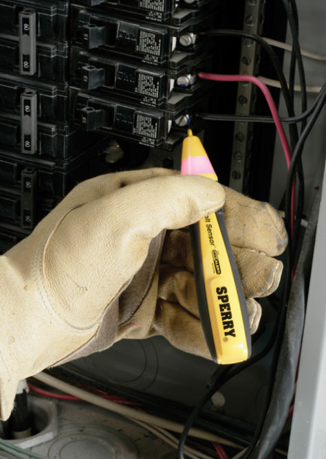
Using a voltage tester tool, test for the presence of voltage at each component (outlet, switch, circuit breaker). Some voltage testers will beep and/or show a red color when it detects voltage.
Try to determine which components (outlets, switches) are on a circuit and in what order.
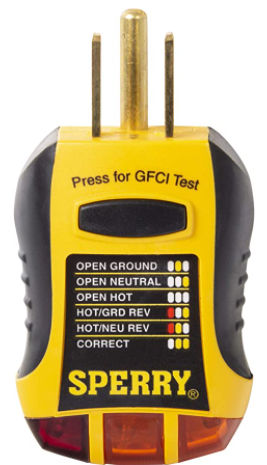
Plug an outlet tester into the outlet to check whether the wires were installed correctly. For example, the outlet may have an open neutral meaning the white wire may be disconnected. Even if the black (hot) wire is connected, if the white (neutral) wire is disconnected, then the outlet, and all downstream outlets, won’t work. Using an outlet tester is the easiest way to test continuity in wires.
If an open neutral exists, open the outlet and verify the white wire is installed correctly. If the outlet tester still reports an open neutral, then the white wire may be loose or disconnected on the other end, e.g. at the circuit breaker. If the white wire is connected at the circuit breaker, then it could be disconnected somewhere in between both end points, which could happen if a rat chewed on the wire. In that case, new wiring needs to be added.
If the outlet tester reports an open ground (ground wire not connected), then the outlet will still work but it’s not safe to use.
Use the outlet tester on ALL outlets in a circuit. A disconnect in one outlet can cause all downstream outlets to not work.
In order for an outlet to work, electricity must flow from the black wire into the outlet and out from the white wire thereby creating a loop. The outlet tester is one way to check for continuity. Another is by using a multimeter. A multimeter can also be used to trace wires through walls to see to find each end point.
If an outlet sort of works, e.g. a light connected to it is dim or flickers, it could be because there are too many devices drawing too much power to it or the voltage in the circuit is too low, e.g. 85 V instead of 120 V. To determine the actual voltage on the line, you can use a multimeter.