I hate seeing lots of cables everywhere. In this post, I will list various options for managing and hiding cables.
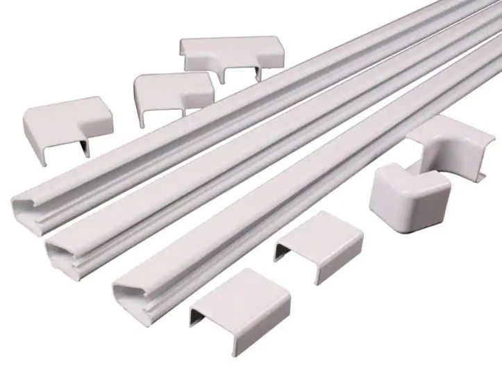
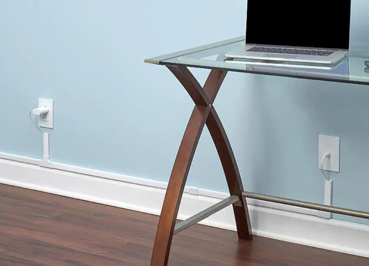
Cord Covers / Cable Raceways
These are useful for hiding cables in a paintable conduit. The cable cover can be made of plastic or metal. Some have an adhesive backing and some you can screw to a wall. They come in various sizes and lengths and include various connectors. These are great for when you can’t hide cables behind or underneath something.
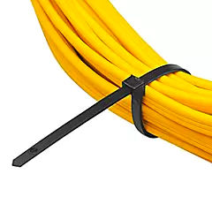
Cable Ties
Cable ties are great for holding multiple cables together. Usually, once you pull to tighten the cable tie, you can’t release it.
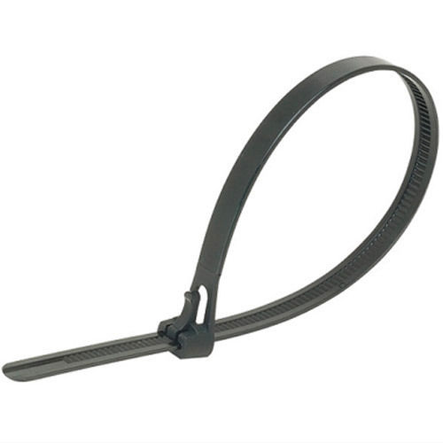
If you need to release a cable tie, you can buy the releasable type.
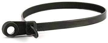
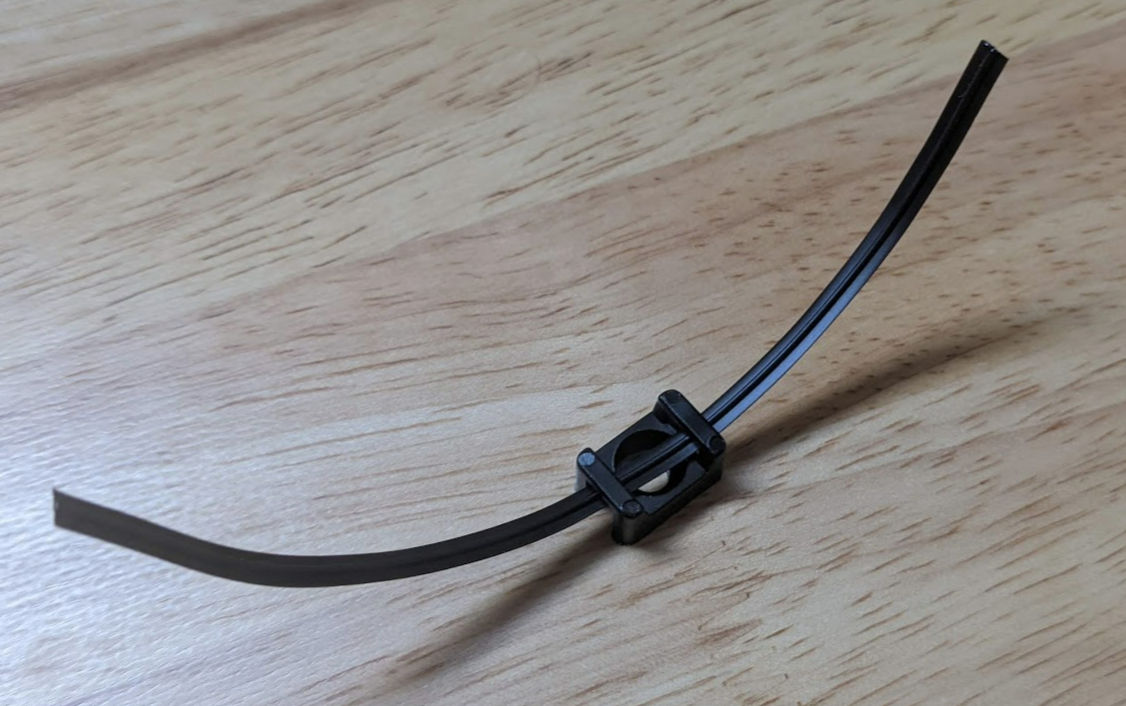
Cable Tie Base Mount
Cable ties will bundle cables together, but oftentimes you’ll need to attach them to a wall or something. You can buy cable ties with a screw hole.
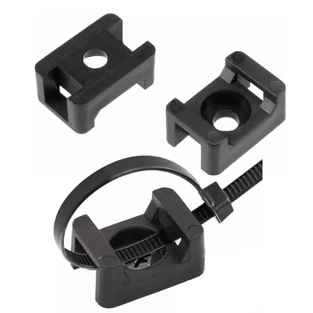
However, you may have a hard time finding these with releasable cable ties. In that case, you can buy the base mounts themselves and insert releasable cable ties in them, or just use a twistie tie.
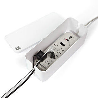
Cable box
Oftentimes, you’ll have an ugly power strip with a bunch of cables going to it. You can hide this ugliness in a cable box.
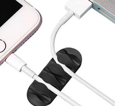
Cable Clips
If you need to clip some cables in a removable way, cable clips with adhesive backing can help with that.
The article is based on this YouTube video. These instructions are similar for adding 120 V circuits as well.
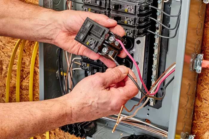
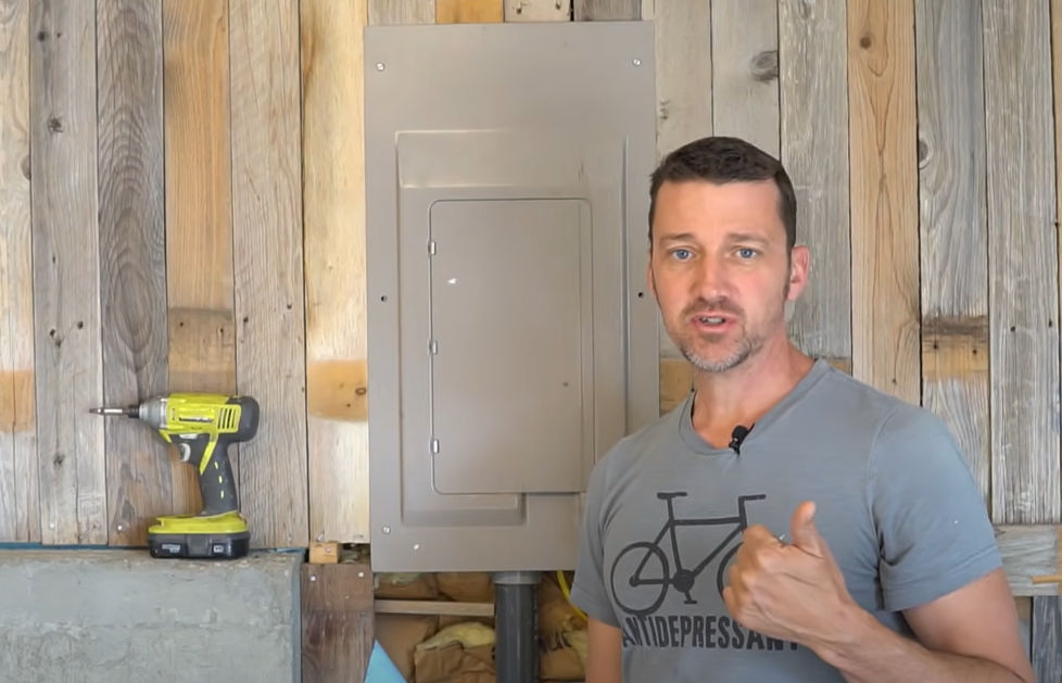
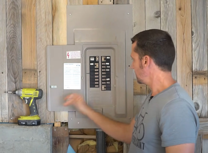
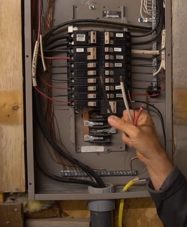
When you open the panel door, verify that you have empty slots to put a one-pole (120 V) or two-pole (240V) circuit breaker. If you don’t, you may need to upgrade your panel to a larger one.
Unscrew the screws and remove the panel cover.
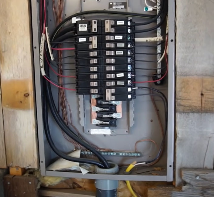
You will usually see two large cables coming into the box.
One black wire = + 120
Other black wire = – 120
Voltage diff between the two = 240
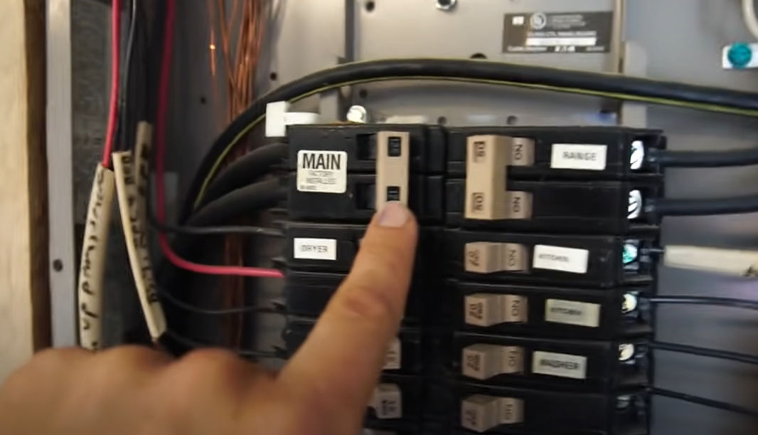
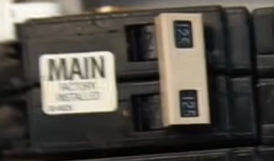
The 2 black wires go into a main breaker.
In this example, the main breaker supports 125 amps, and the main breaker is located in the same panel as the circuit breakers.
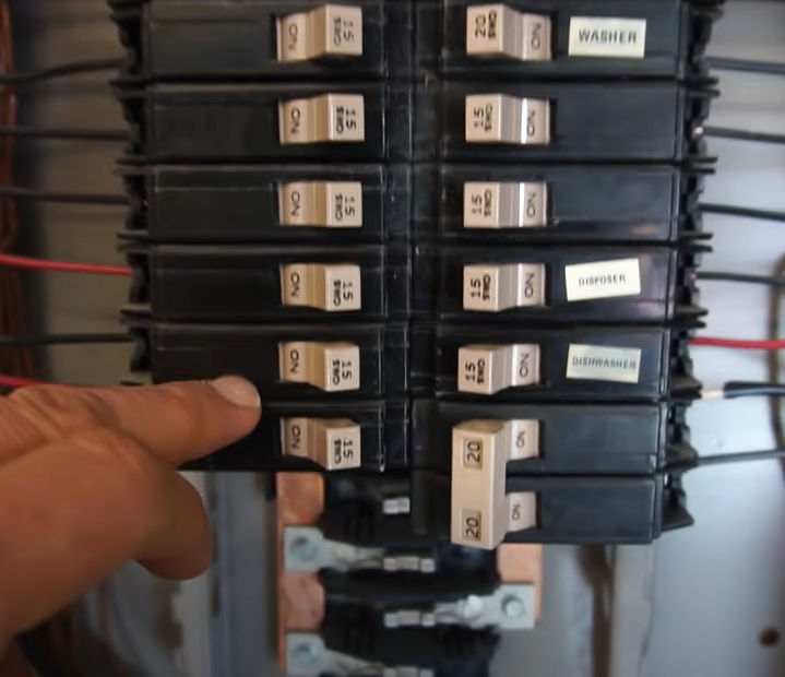
The electricity then goes into the two left and right rails. Usually, you’ll have some 120 V / 15 A circuit breakers for general power, 120 V / 20 A circuit breakers for kitchen and bathroom power, and 240 V / 20 A double circuit breakers for an electric dryer.
Electricity flows from the rail through the circuit breaker through the wires.
Everything in the box is hot until you turn off the main breaker. Once you turn off the main breaker, only the 2 black wires and the terminals they are connected to are still hot.
In my home, the main breaker is located in a separate panel outside whereas my circuit breaker panel is in the garage. This is safer because once you turn off the main breaker outside, there are no hot / live wires in the circuit breaker panel.
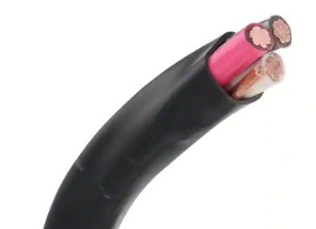
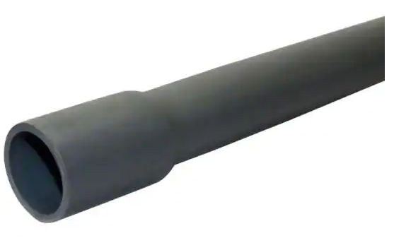
The “6/3” identifier means this cable is 6 gauge and has 3 conductor wires and 1 ground wire for a total of 4 wires. The max amperage that this cable supports is 55 amps as indicated in the chart below.
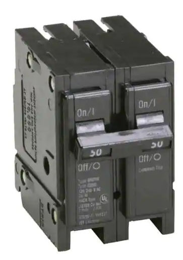
Find the right kind that fits your circuit breaker box. My breaker box brand is Challenger. From the time when Challenger went out of business in the 90s, they were bought by different companies until Eaton/Cutler-Hammer finally got a hold of them. So, in my case, I can buy Eaton BR/C breakers.
The amperage of the circuit breaker must be less than or equal to the max amperage of the cable connected to it to prevent the cable from melting and causing a fire.
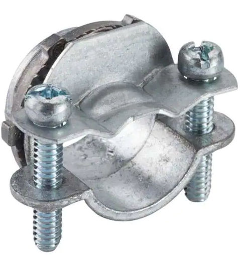
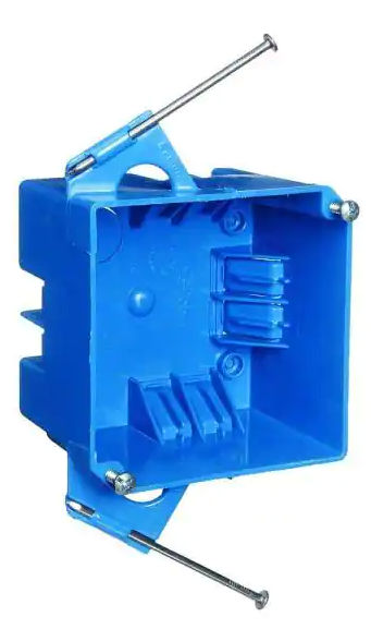
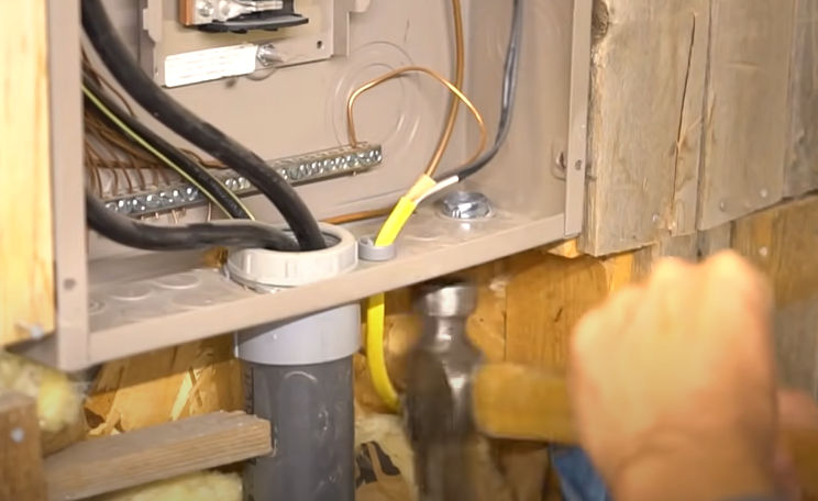
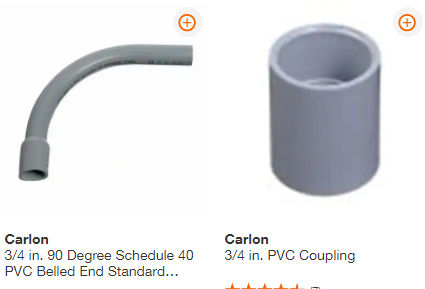
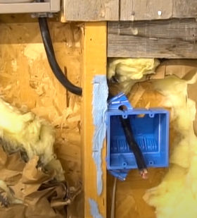
When you knock out a hole, make sure you knock out a 3/4″ center hole in one of the sides, not a smaller 1/2″ hole. If you accidentally knock out a 1/2″ hole, you can seal it with one of these:
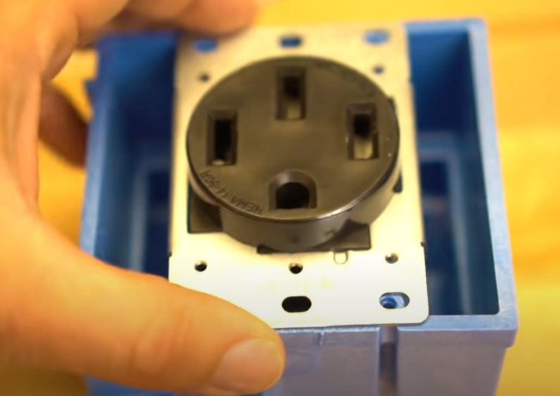
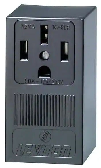
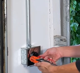
Note: The cable is very thick and difficult to bend. Using the Leviton outlet is MUCH easier than making your own outlet because with the Leviton, you don’t need to bend the cable at all.
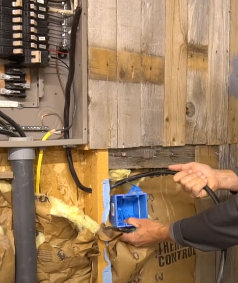
Run the cable through the stud and into the breaker box.
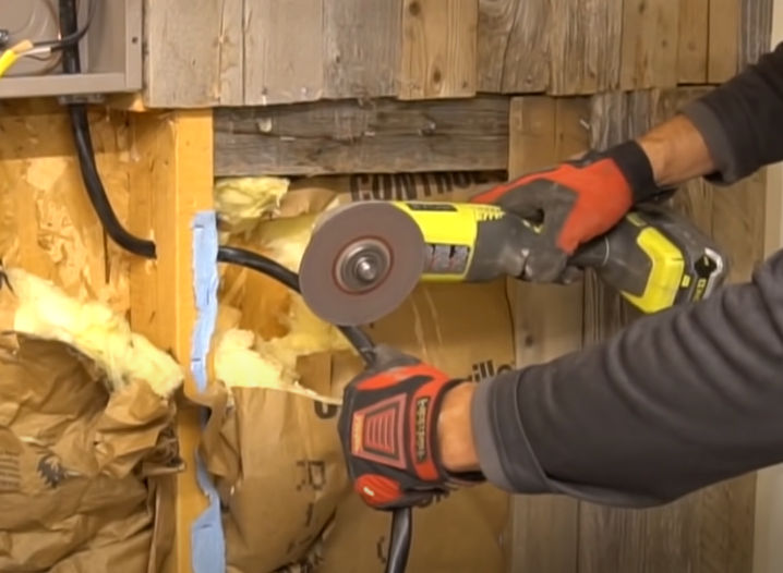
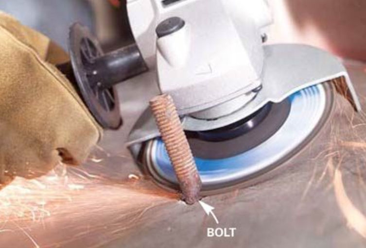
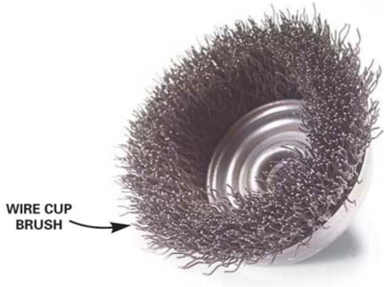
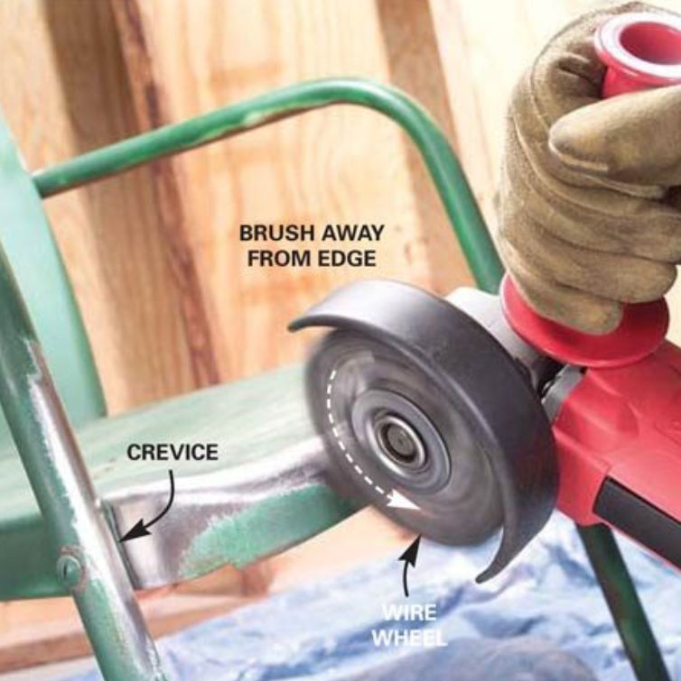
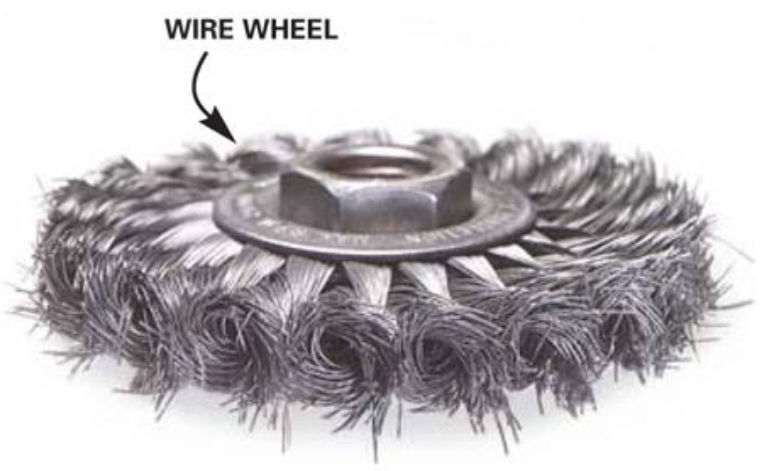
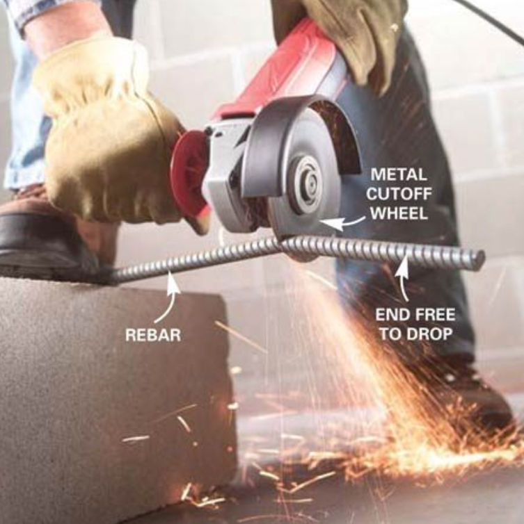
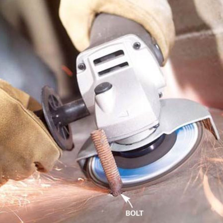
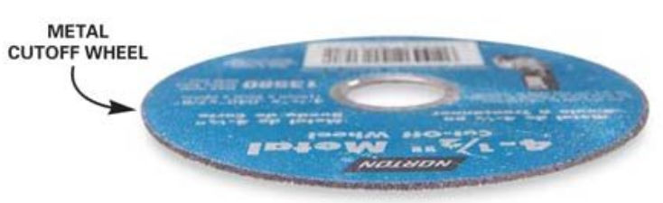
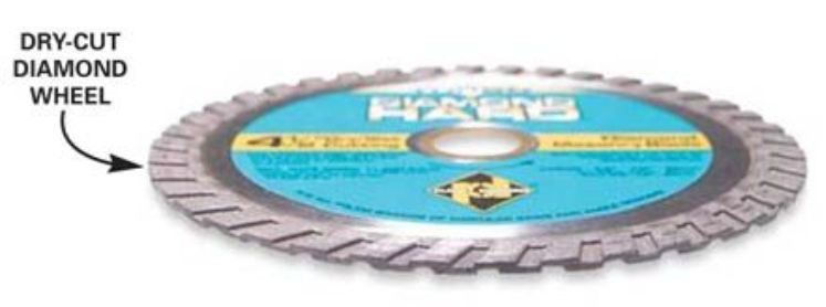
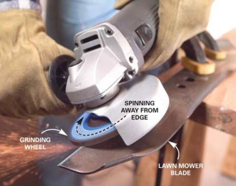
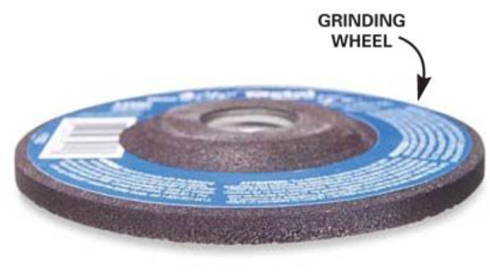
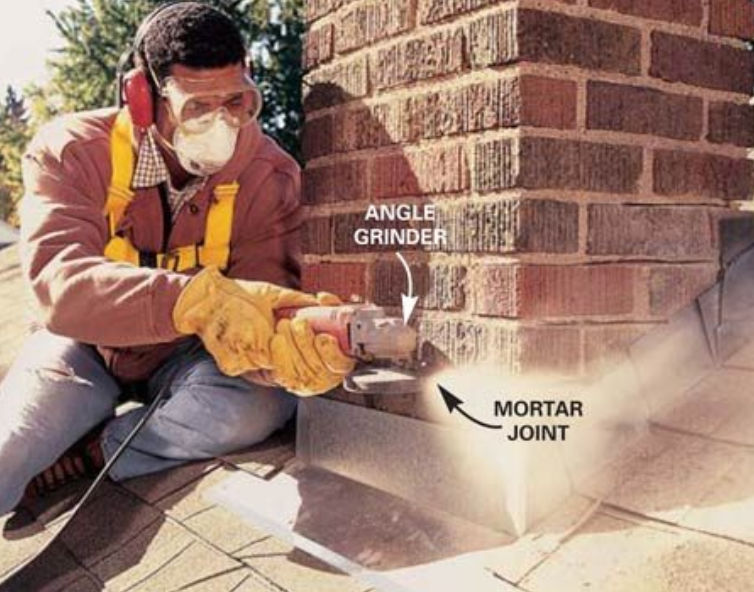
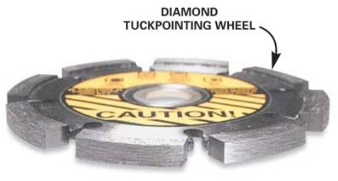
The cable can be hard to cut. If you can’t cut it with scissors or snips, you can use an angle grinder.
For ease of work, feed the thick wire into the electrical box before attaching box to stud.
Strip the wires in the cable. First, slit the exterior jacket / sheathing lengthwise using a sharp utility knife. Then, use a wire stripper to cut just the sheathing layer using the flat blade part. You can’t use the various round blades because the cable is too thick.
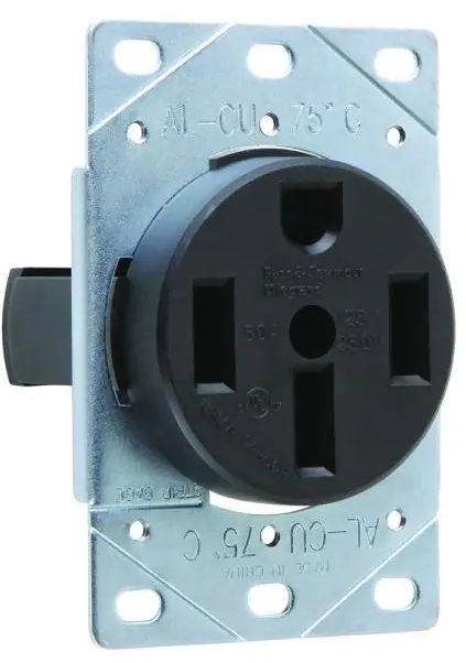
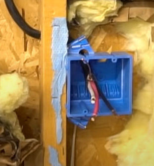
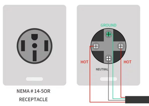
Attach the wires to the outlet.
The red and black (hot) wires are interchangeable and connect to the gold screw terminals.
The white (neutral) wire goes to the silver screw terminal.
The bare copper (ground) wire goes to the white screw terminal.
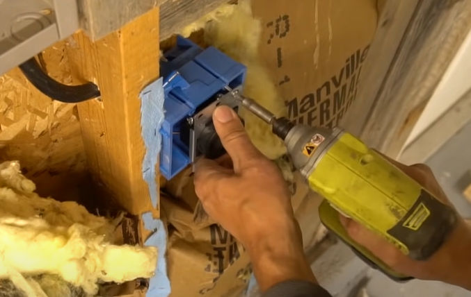
Screw the outlet to the box.
Strip the wires on the other end of the cable. Make sure the main circuit breaker is off.
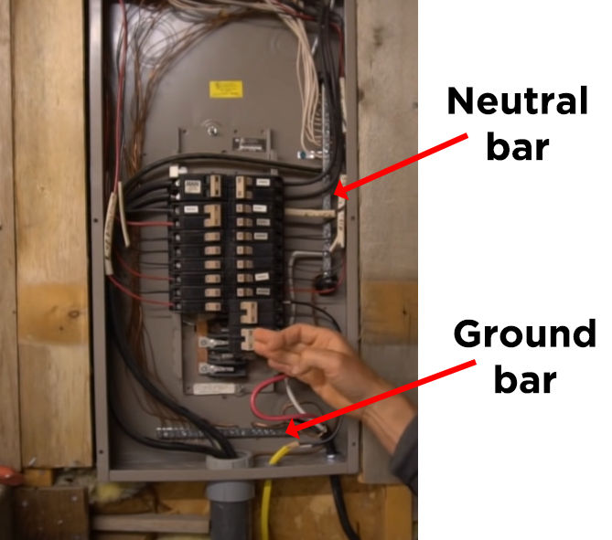
Connect the white (neutral) wire to the neutral bar.
Connect the bare copper (ground) wire to the ground bar.
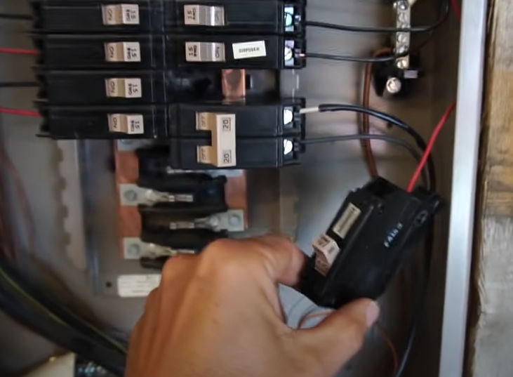
Connect the two red and black (hot) wires to the 240V circuit breaker.
Insert the circuit breaker.
Turn on the main breaker and then turn on the new 240 V circuit breaker.
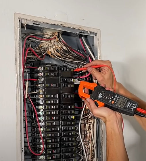
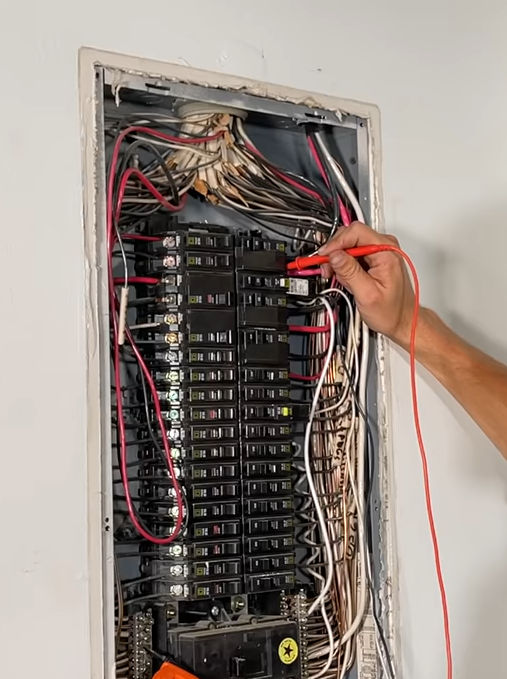
Test voltage
Hot (red) to hot (black) should be about 240 V.
Hot (red) to neutral should be about 120 V.
Hot (black) to neutral should also be about 120 V.
Do the same voltage test at the receptacle.
Here’s how mine came out.
It would have been more expensive and a hassle to put the outlet by the garage door, so I just put it next to the circuit breaker panel. I’ll just use an extension cord to reach the garage door.
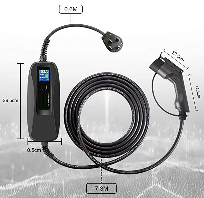
You can buy this EV charger cable on Amazon for $330.
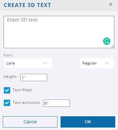
When drawing rectangles, you can specify length & width by separating the measurements with a comma. For example: to draw a two foot by four foot rectangle, you can enter 2', 4' into the measurement box. The order of the measurements matches the order of the axes (R, G, B). For example: Red, then Green; Red, then Blue; or Green, then Blue.
When items are pre-selected, you can click anywhere in the model to begin moving them, and then click anywhere to set them down. This is an effective way to move things precisely and/or align things to other things.
Click the red crosshairs that appear on the bounding box of an object to rotate that object.
After moving a copy, you can type a number followed by the X key and then press Enter to create an array of copies.
Rotate, stretch, distort, or copy items or objects along a rounded path.
Tool Operation
(Optional) Preselect the items or objects you want to rotate.
Click on an item or object to both make a selection and set the center point of rotation.
Move cursor to indicate start point of rotation.
Click to set starting point of rotation.
Move cursor to indicate end point of rotation.
Click to complete rotation, or enter angle in degrees.
Modifier Keys
Ctrl = Toggle rotate a copy.
Before first click, hold Shift to lock protractor inference.
Before first click, use arrow keys to toggle the protractor inference lock direction (→ = Red, ← = Green, ↑ = Blue, ↓ = Parallel).
After first click, use arrow keys to toggle rotation inference lock direction (→ = Red, ← = Green, ↑ = Blue, ↓ = Parallel/Perpendicular).
Tips
Esc = Cancel operation.
During Step #2 of the tool operation steps above, you can click-drag the protractor along an edge or axis to set an axis of rotation.
After rotating a copy, you can type a number followed by the letter X and then press Enter to create a rotated array of copies.
When inputting rotation values into the Measurements box, you can enter either an angle of rotation, in degrees (for example 45 Enter),or a slope expressed as a rise:run architectural slope notation (for example 4:12 Enter).
(Optional) Preselect the items or objects you want to scale.
Click on a face or object.
Click on a Scale grip.
Move cursor to resize or stretch item or object.
Click to finish scaling item or object.
Modifier Keys
Ctrl = Toggle scale about center.
Shift = Toggle uniform scale.
Tips
Esc = Cancel operation.
Click a corner grip for 3-way scale. Default = Uniform. Pressing Shift = Non-uniform.
Click a midline grip for 2-way scale. Default = Non-uniform. Pressing Shift = Uniform.
Click a center grip for 1-way scale. Default = Non-uniform. Pressing Shift = Uniform.
When scaling an item or object you have the option to enter either a scale factor (for example 2.5 Enter will make the things you’re scaling 250%, or two and a half times bigger), or you can simply input the size that you want the thing you’re scaling to be (for example, if scaling up along the blue axis direction, 6' Enter will make the selection six feet tall).
It’s possible to activate multiple section planes at the same time, as long as the section planes are in different contexts. For example, you can activate one section plane through the model, and then activate another section plane through a group or component object and have both planes active at the same time.
Measure angles and create angled guide line entities.
Tool Operation
Place protractor’s center at vertex of angle.
Click to set vertex. (Alternatively: click and drag first point to set rotation plane.)
Move cursor in circle until touching start of angle.
Click to set start of angle.
Move cursor in circle until touching end of angle.
Click to measure angle.
Modifier Keys
Ctrl = Toggle create guide lines.
Before first click, hold Shift to lock protractor inference.
Before first click, use arrow keys to toggle the protractor inference lock direction (→ = Red, ← = Green, ↑ = Blue, ↓ = Parallel).
After first click, use arrow keys to toggle rotation inference lock direction (→ = Red, ← = Green, ↑ = Blue, ↓ = Parallel/Perpendicular).
Tips
Esc = Cancel operation.
When inputting rotation values into the Measurements box, you can enter either an angle of rotation, in degrees (for example 45 Enter ), or a slope expressed as a rise:run architectural slope notation (for example 4:12 Enter).
Click anywhere in the model to place the camera. The camera will be positioned above the point where you click, at the eye height distance specified in the measurements box.
(Optional) Click and drag from one point in the model to another point in the model to create a target camera. The point you drag from will be the exact location where the camera will be positioned, the point you drag to will establish the camera target.
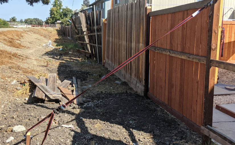
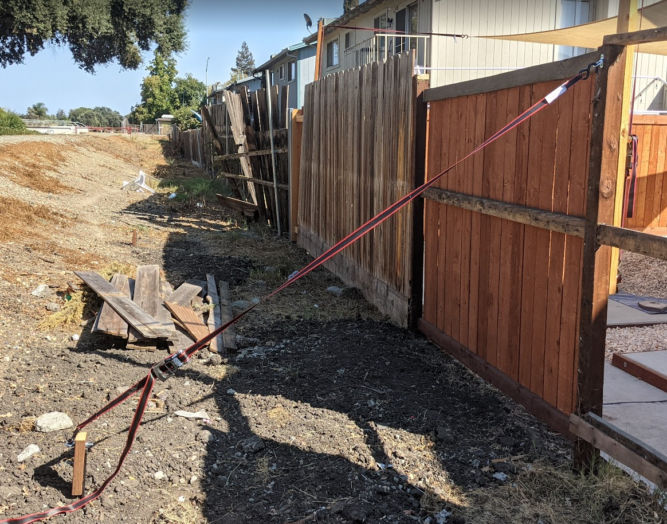
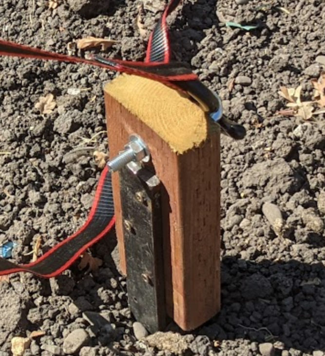
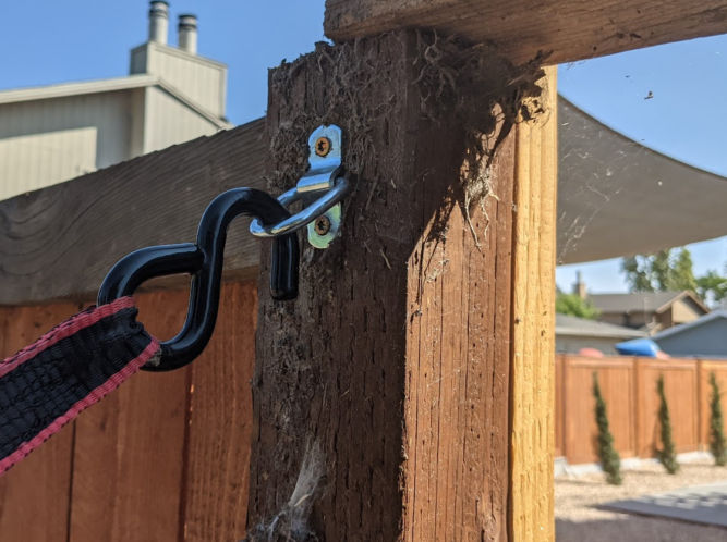
One of my fence posts on a rental property was leaning over due to the previous owner not securing it correctly in the ground. To make matters worse, I use the fence post to secure a ratchet strap attached to one of 4 corners of a sun shade. Since I didn’t feel like redoing the fence post, and since the back of my property is empty, government land beside a slough, I decided to just pull the fence post back into position using a ratchet strap. It was quick and easy and worked perfectly.
If you don’t feel like redoing a leaning fence post or need a temporary fix, here’s what you can do.
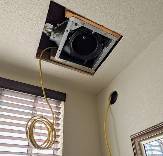
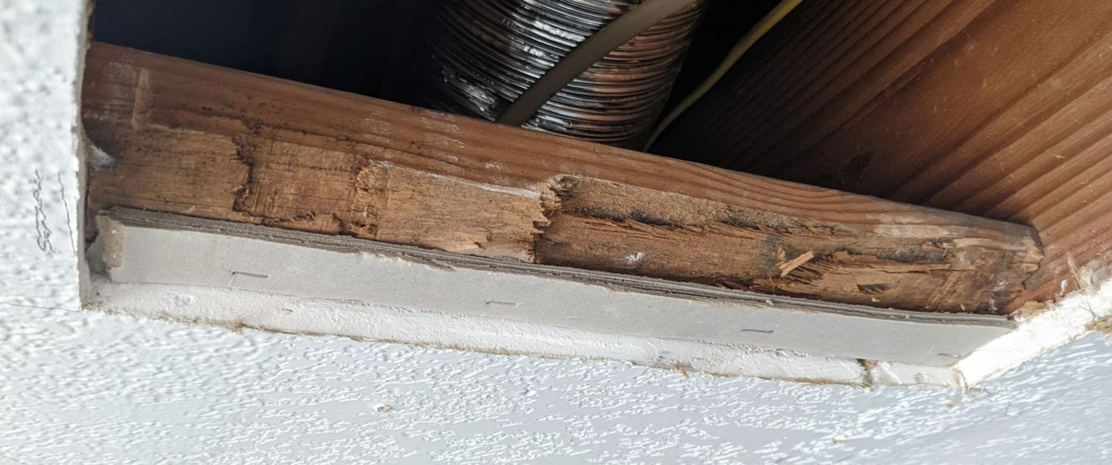
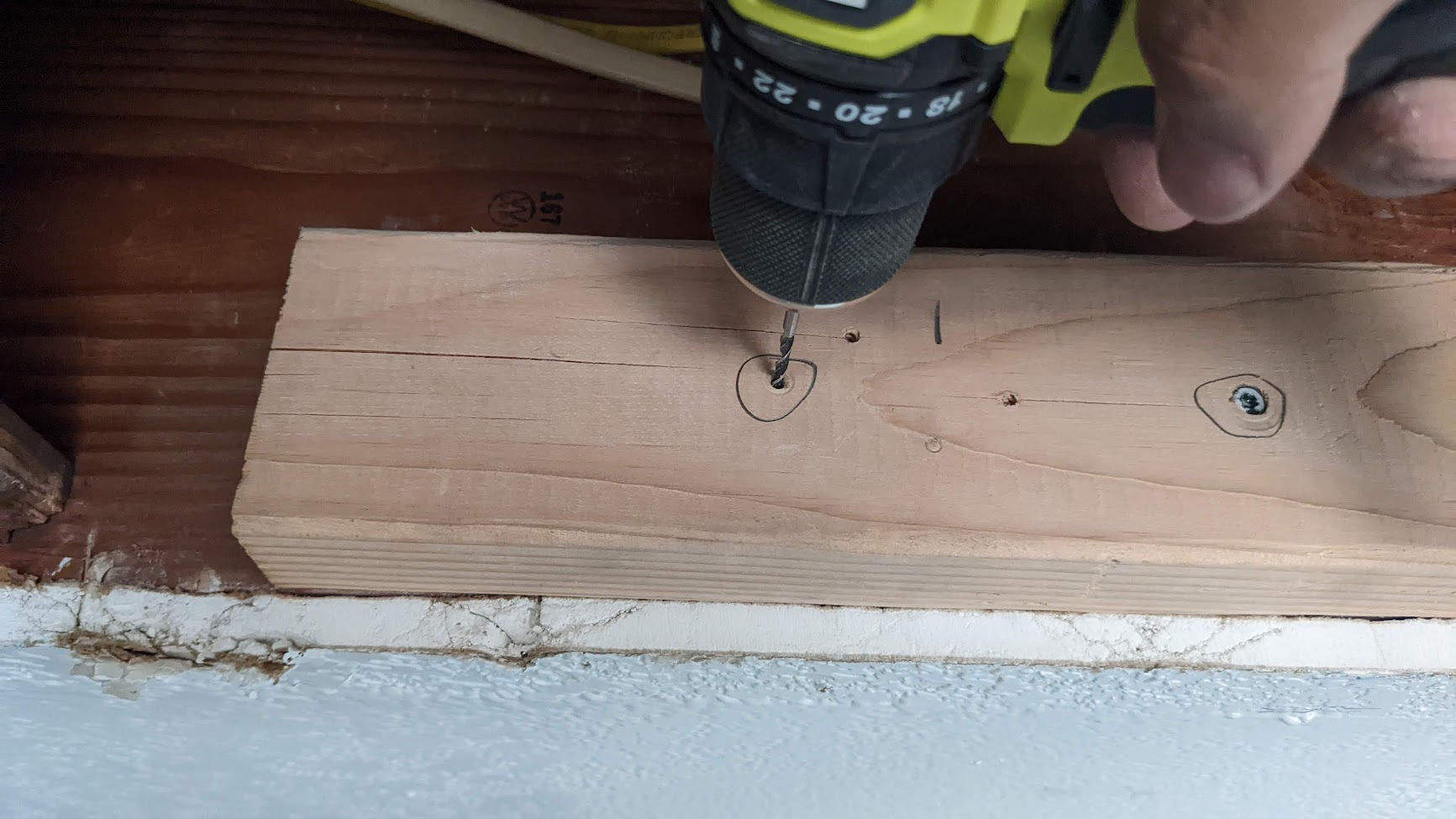
Let’s say you want to install a bath exhaust fan in a bathroom that doesn’t have one. You’ll need to cut the wall or ceiling where the fan will go and you’ll also likely need to make holes in the wall or ceiling to run electrical wiring.
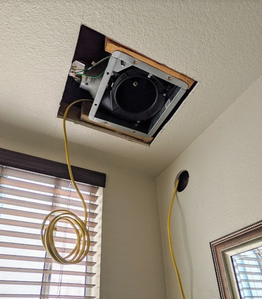
In the photo above, you can see that I made two types of openings:
Circular opening
Square opening
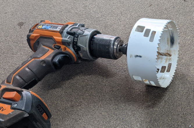
Making a Circular Opening
For the circular opening, I just used a hole saw attached to a drill. The benefit of this is it creates a clean, perfectly circular hole and you can reuse the cut drywall later to patch the hole. This type of hole can be made anywhere – it doesn’t need to be near or over a stud or joist.
Patching a Circular Opening
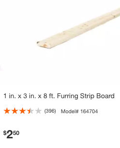
To patch a circular opening, I use a 1″x3″ piece of furring strip wood.
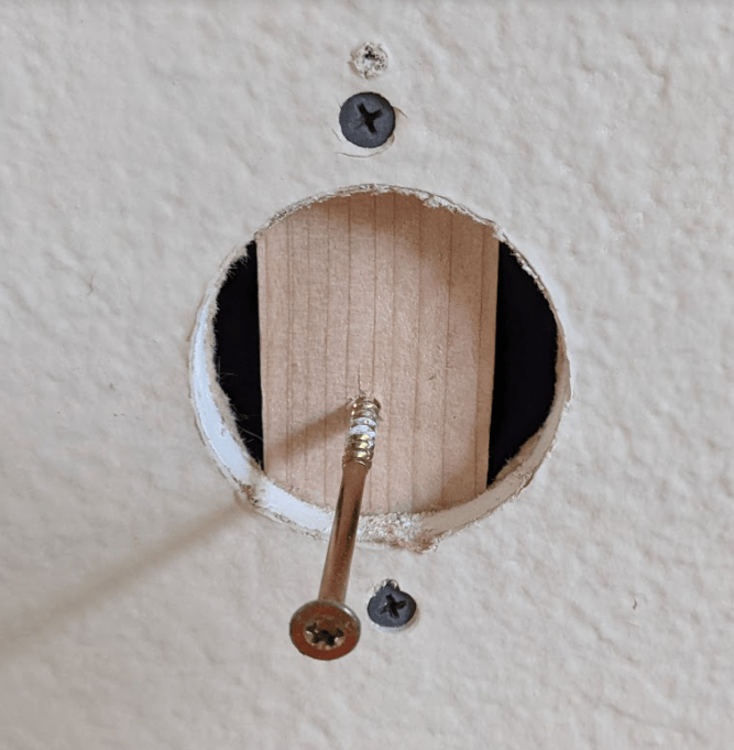
Partially drill a long screw in the middle of a piece of furring strip that is about 3 inches longer than the diameter of the hole. Insert the wood into the hole as pictured below. Then, drill 2 screws while pulling the long center screw so that the wood doesn’t move around. Now you’ve created a backing for the drywall to be screwed into.
Remove the center screw and screw the drywall into the wood.
Making a Square Opening
For the square opening, I like to use a reciprocating saw – specifically, the Milwaukee 12V mini cordless saw because it’s small and lightweight. Use a stud finder to find the studs or joists and draw an outline of the square you want to make such that the square (or rectangle) goes to each stud or joist. Then, try to make a clean rectangular cut so that you can reuse the drywall.
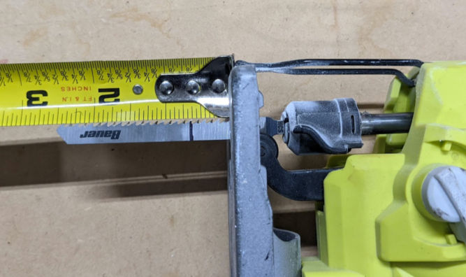
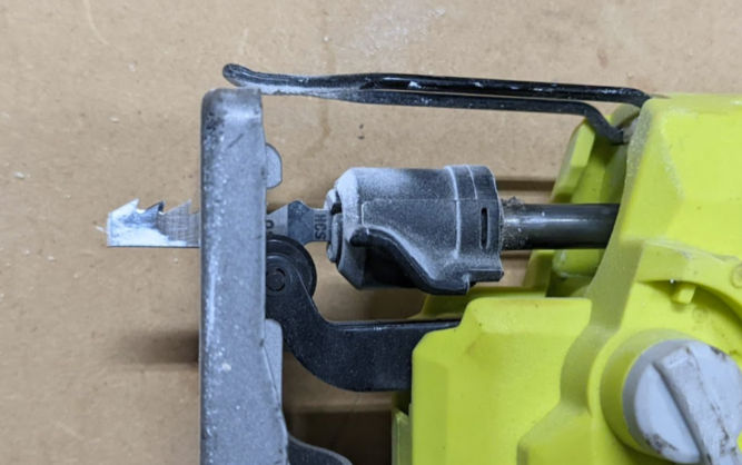
UPDATE: With a reciprocating saw, you may accidentally cut some wires. An easier and safer way is to use a jigsaw with a shortened blade. Insert a blade into your jigsaw, extend the stroke as far as possible, mark 1/2″ or 5/8″ from the jigsaw shoe (bottom part), then, using a bolt cutter, cut to shorten the blade. Now, you can use your jigsaw to safely and easily cut drywall.
Patching a Square Opening
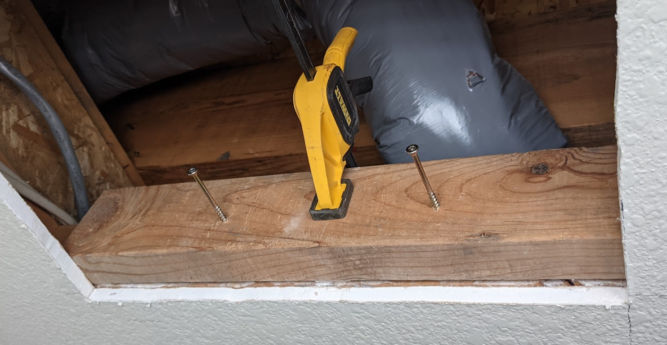
To patch a square opening, I use a 2×4 piece of wood to fur out the studs or joists to create a backing for the drywall will be screwed into. Pre-drive the screws into the wood a little bit and then clamp the wood to the joists to make fastening the wood piece easier. The 2×4 should be longer than the opening so you can position it such that the cut drywall will be level with the existing drywall when you go put it back in.
When you put the cut piece of drywall in the opening, if the four edges are not level with the four edges of the existing drywall, then you either must
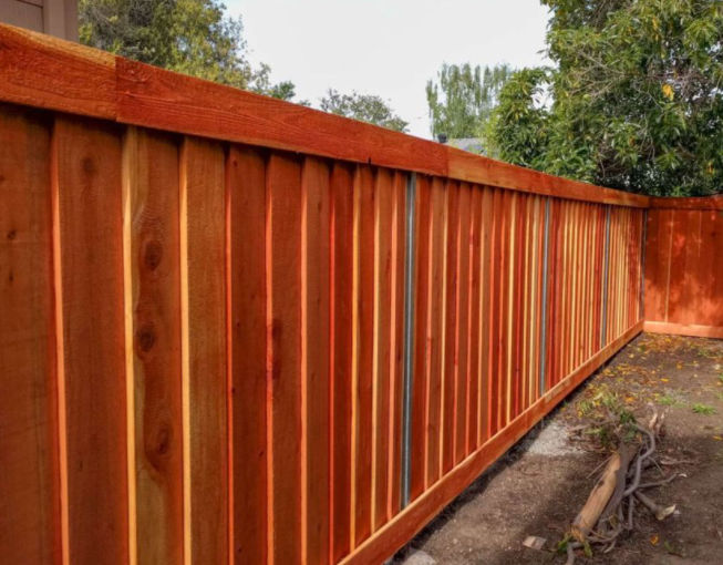
I recently had to rebuild a bunch of fences on a new rental property. As you may already know, the hardest part is digging the holes and building the frame. This article explains step by step how to quickly and correctly build a fence frame.
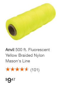
1. Run string from one end of new fence to the other end near the ground
In order for the fence to be straight, we need to make a straight line from both ends. Since we haven’t dug holes yet, we put the string near the ground so we can mark where we want the holes for the fence posts to go.
Nylon Mason’s line is thin and can easily break. Instead, you can use paracord.
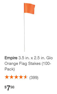
2. Mark post hole locations
Depending on the existence of neighboring fences, we may or may not need posts at the ends. Mark where the post holes will go. Each fence panel between posts will be 8′ long. For marking the locations, you can use a wood stake, metal stake, flag stake, or spray paint. I prefer using flag stakes.
3. Dig fence post holes
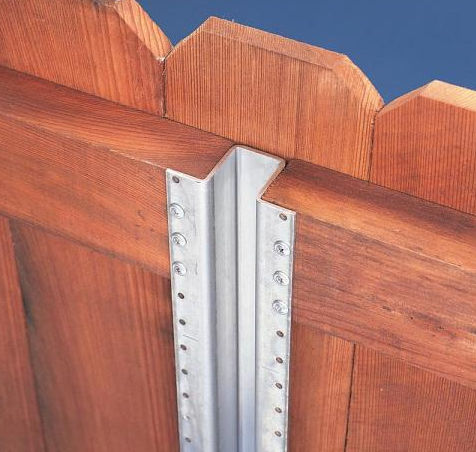
Post type
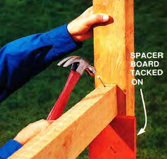
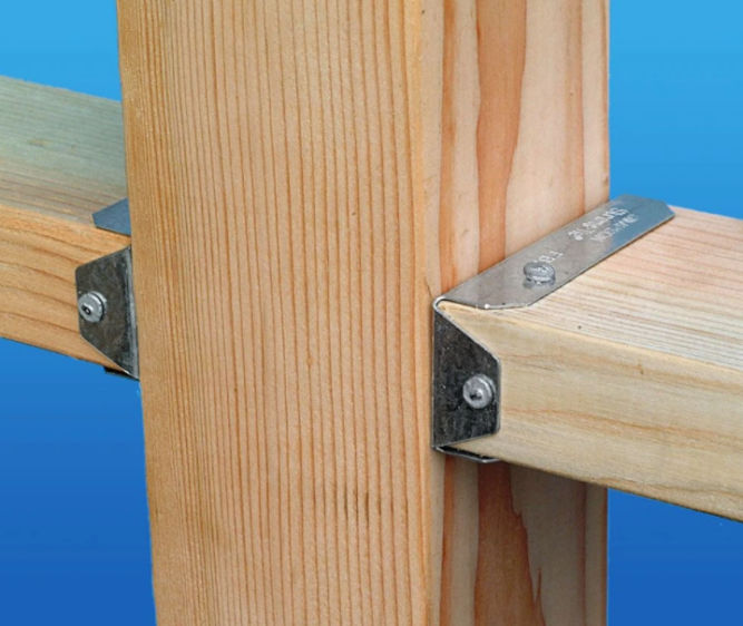
Normally, people use 8′ long 4×4 pressure-treated wood for fence posts. If you do that, then the horizontal 2x4s (rails) will have to be toenailed into it or secured using metal brackets.
Toenailing 2×4 rail to fence postFence rail bracket
Either way, that’s a lot of work, especially if you later decide to make adjustments. Also, the wood can rot,weaken, and become warped over time. For these reasons, I just spend the extra money and buy steel fence posts.
The post hole diameter should be about 3 times the width of the post. Since the steel posts are 3.5″ wide, then the hole should be about 10.5″ in diameter.
Post hole depth
The post hole depth should be 1/3 to 1/2 the post height above the ground. Since we want our fence to be the standard 6′ tall, and the steel posts are 7.5′ long, we’ll make our holes 2.5′ deep.
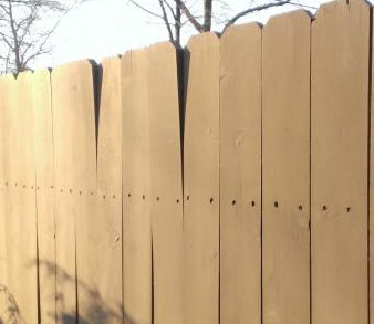
Top of fence
The height of the fence post and the top rail above ground will be 5′. Therefore, the top one foot of the 6′ tall vertical fence boards will be above the top rail. The problem with this is the top one-foot portion of the fence boards can warp.
To fix this, you can screw a horizontal piece of wood (2×3 or 2×4) at or near the top of the fence boards on the side where the fence rails are.
Soak the ground
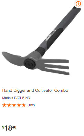
Before digging holes, you’ll want to soak the ground, preferably overnight. This will make it much easier come time to dig. The deeper you dig, the harder the soil. You can dig a small hole first using a hand digger.
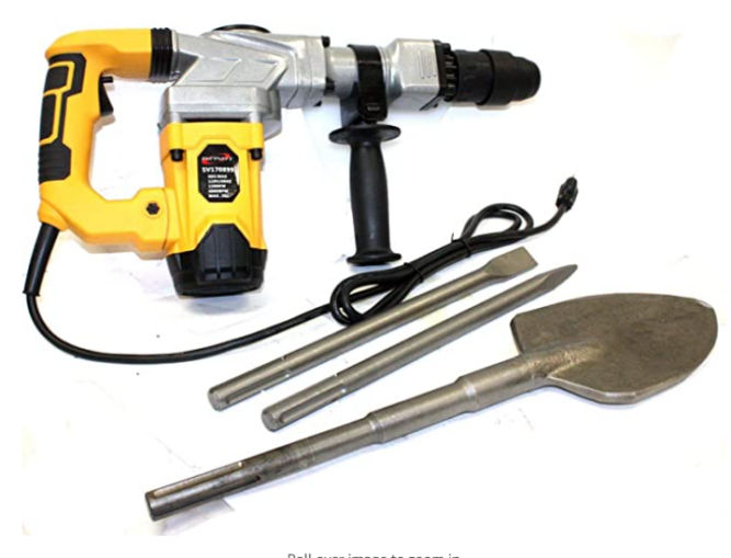
Or, preferably, you can just use a jackhammer with a spade bit.
Digging tool
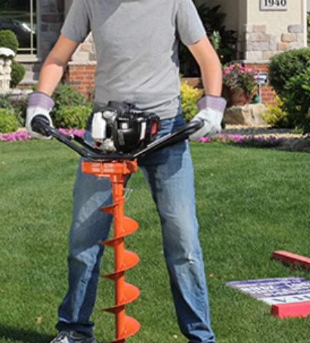
To dig holes, the easiest and cleanest way is to use a gas-powered earth auger. You can rent one from the Home Depot ($55 for 4 hours). You can choose from a variety of auger bit diameters. Choose a 10″ or 12″ diameter auger bit.
When you are digging, if you can’t dig any deeper, then stop and pour water into the hole and let the water drain. You can then dig again.
You may run into roots and rocks while digging with the auger. In this case, you’ll need to cut the roots using a reciprocating saw or break up the rocks using a jack hammer.
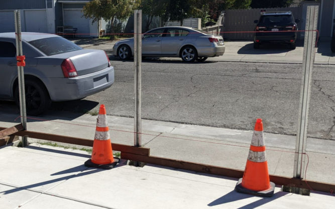
4. Tie a string to both end posts
Now that you have 2.5′-deep holes, you can insert the steel posts at each end. Tie string or paracord from one end post to the other both near the bottom and top of each post. The purpose is to adjust the middle posts to be aligned with the end posts. Later on, when concrete is poured into the middle post holes, the middle posts should touch the string.
In the photo below, there are a total of 3 posts and 2 string lines connected to each end post.
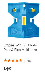
5. Plumb and brace the posts
Adjust the position of each post using a fence post level and check for plumb.
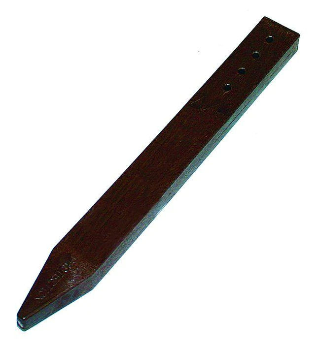
To hold the posts in place, if the surrounding ground is dirt, brace them using stakes. I prefer hitting a 2′ long steel stake straight into the ground and then screwing a piece of wood horizontally between the steel stake and the post. The steel stakes are pre-drilled. There should be two braces perpendicular to each other to hold the post plumb.
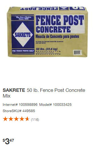
6. Mix and pour concrete
Buy fence post concrete.
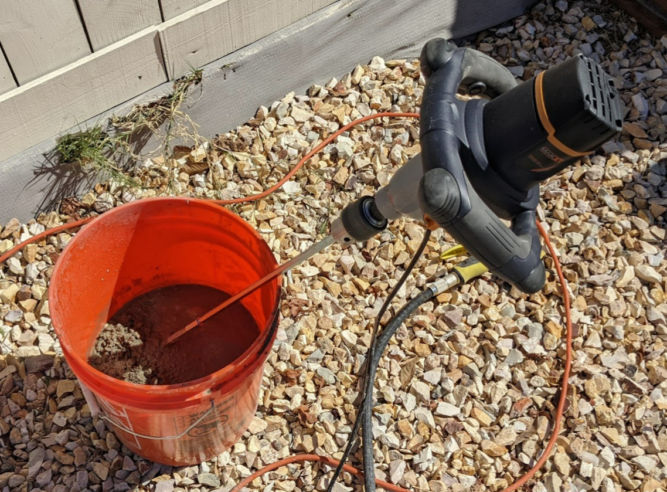
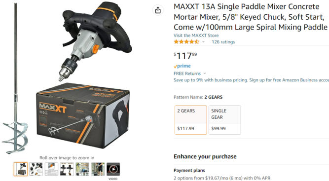
Pour half the bag of concrete in a 5-gallon bucket, add water, and mix using a special mixer for concrete.
The mixer I use is a 2-gear mixer shown below. The first / low gear is for mixing concrete. It has high torque and low speed which is what you want. If you use a high-speed mixer, the concrete mix gets everywhere, creates a mess, and can crack the bucket. I find this particular mixer to be perfect for mixing concrete.
The consistency of the mix should be watery but not too watery. You should be able to pour the concrete mix straight out of the bucket. If you can’t pour the concrete mix, then you need to add water.
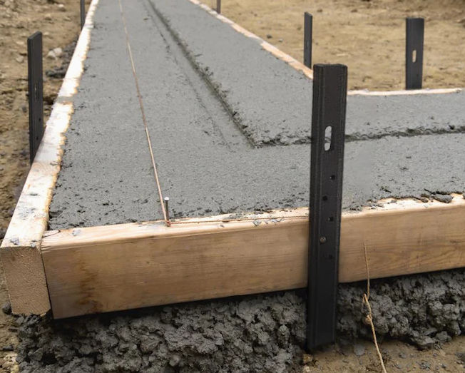
7. Add concrete to the middle posts
Now that the 2 end posts are done, add concrete to the middle posts. If you haven’t braced the middle posts, that’s fine. Once you add some concrete, you can position the posts while the concrete is still wet. Make sure the middle posts touch the top and bottom string lines to ensure a straight fence.
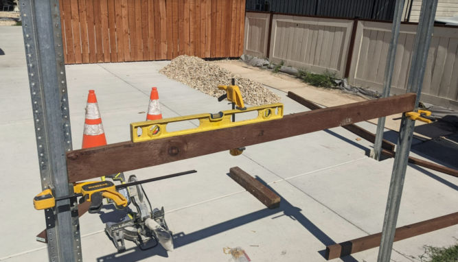
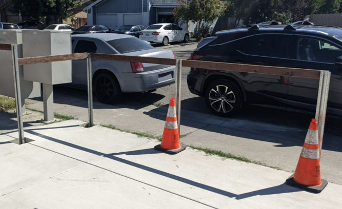
8. Add horizontal fence rails between posts
Once the posts are secure and the concrete is dry, measure how high you want the horizontal rails to be. Then, add clamps to the posts. The clamps will hold the rails in place before you’ve had a chance to screw them to the posts. Secure a level to the top fence rail
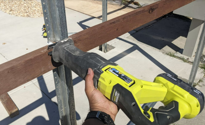
9. Cut posts
Cut the top portion of each post using a reciprocating saw with metal blade.
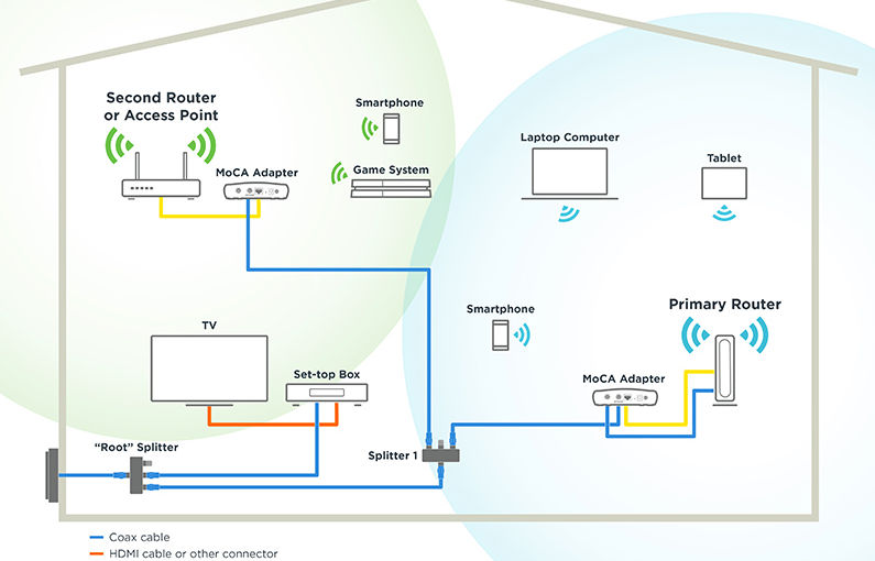
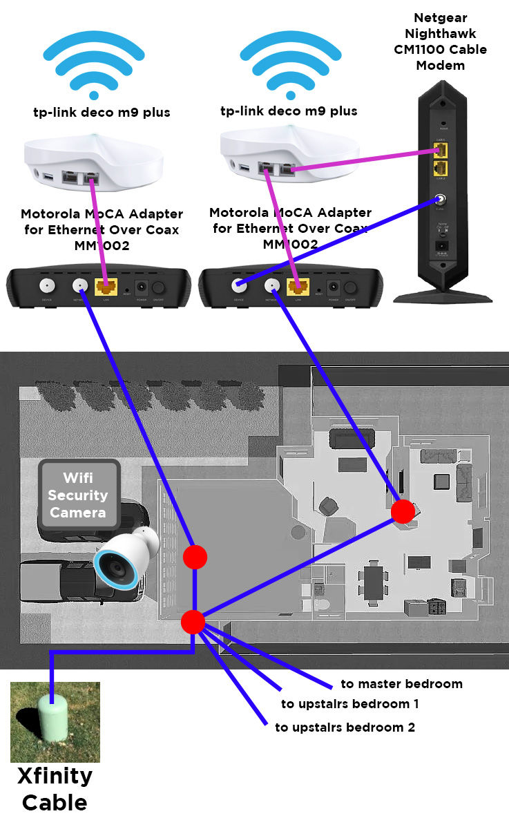
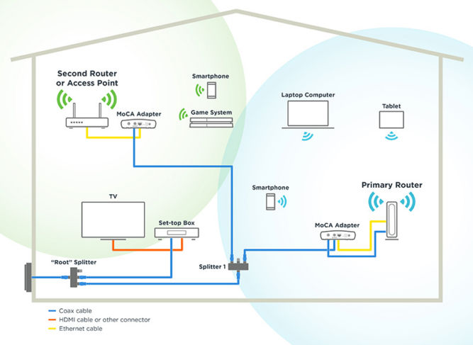
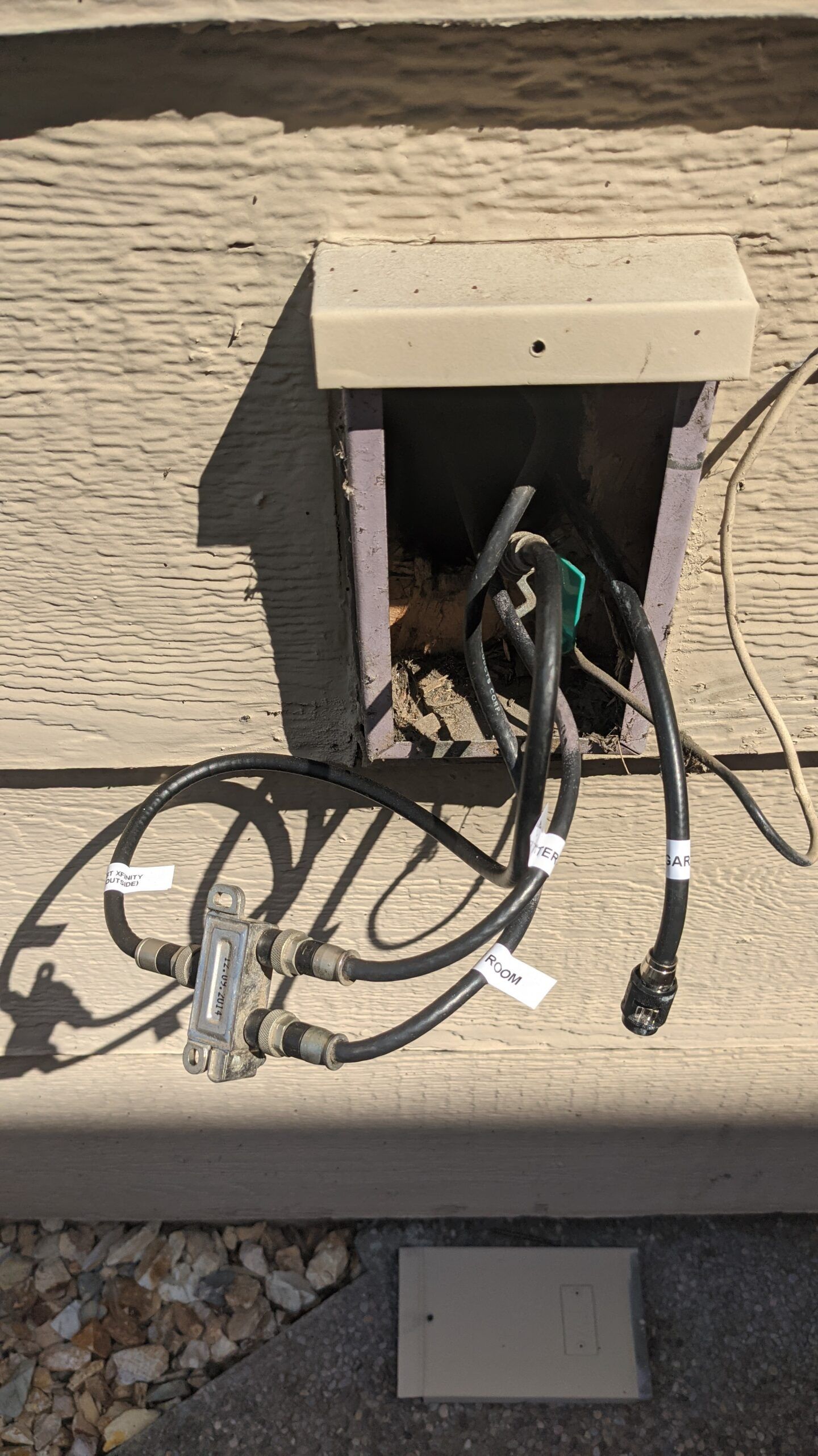
So, in my 2 story house my internet modem is in the family room in the back of the house. The internet comes over coaxial cable by Comcast xFinity 1Gbps. There is a security camera at the front of the house facing the driveway. Every now and then, the security camera would go offline. To spread wifi all over the house, I have the tp-link deco M9 plus AC2200 mesh wifi router (3 wifi access points). The backhaul between access points is wifi, unfortunately. I can’t have a wired ethernet backhaul between access points because running ethernet cable would require opening up walls which is a lot of work. Fortunately, however, there is existing coaxial cabling throughout the house. So, I can use MoCA (Multimedia over Coax Alliance) adapters to bridge ethernet over coax so I can have a wired coax backhaul between access points. This allows the wifi signal at each access point to be much stronger than with a wifi backhaul. There are many diagrams and tutorials online but none that I found were clear enough hence this blog post. Below is my setup with a diagram which should make it clear what goes where.
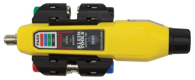
The continuity tester doesn’t work through splitters. Once you’ve tested all cables, you can label them in your junction box like I did below. As you can see, there is a 1 – 2 splitter where the one input is the coax cable from xfinity. The two outputs each go to the master bedroom and family room.
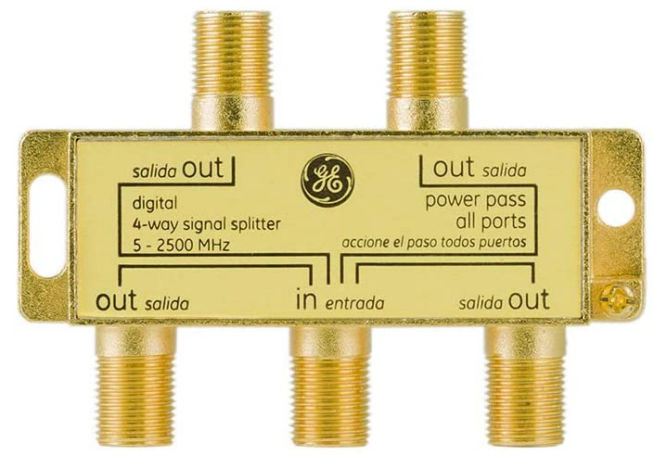
I added a new coax cable to go to the garage but it’s not connected in the picture because I need to add another splitter or replace the existing splitter with a 1-3 (or more) splitter. For MoCA to work, you need a splitter that
is not amplified
goes up to at least 1.5 Ghz (1500 Mhz)
GE Digital 4-Way Coaxial Cable Splitter, 2.5 GHz 5-2500 MHz
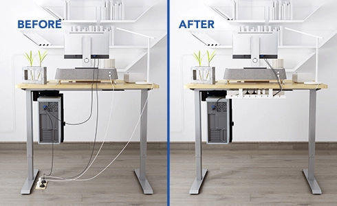
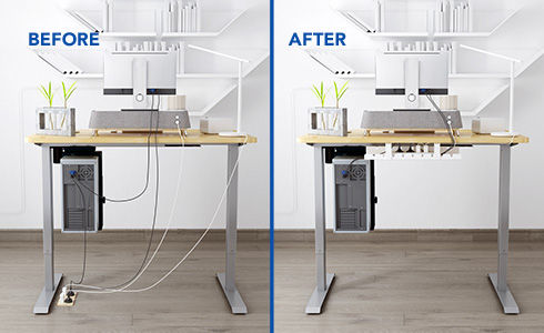
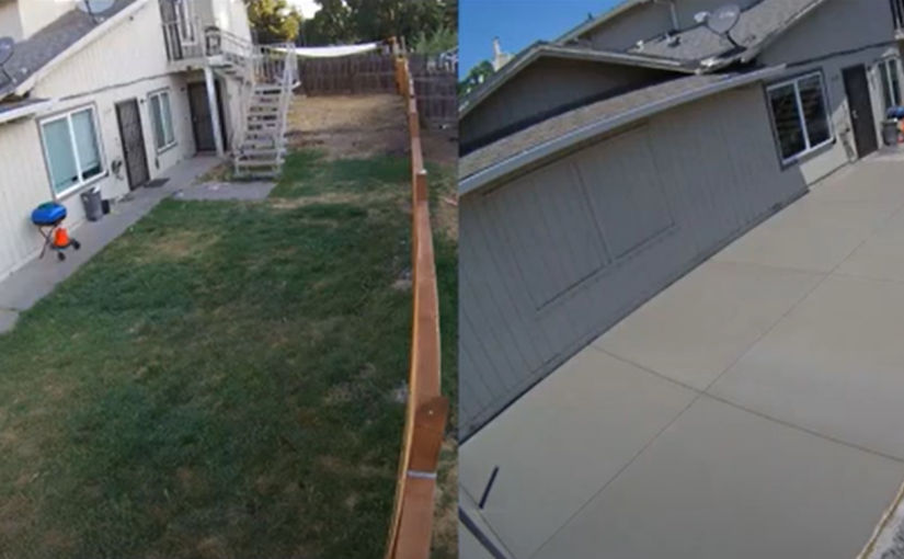
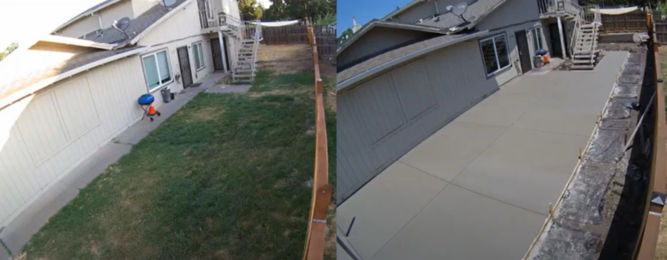
Before and After
BeforeAfter
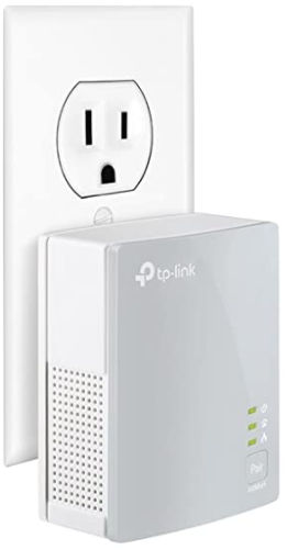
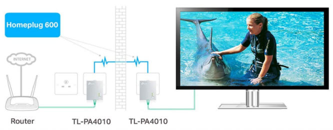
Powerline Adapters
You can also bridge ethernet over your home’s existing electrical wiring using Powerline adapters, e.g.
However, these adapters don’t work if there’s a surge suppressor. Also, there’s a lot more activity in your home electrical wiring that could interfere with the signal, e.g. from the refrigerator, hair dryers, air conditioners, washing machines, and other appliances.
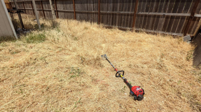
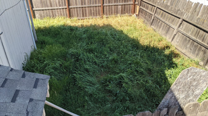
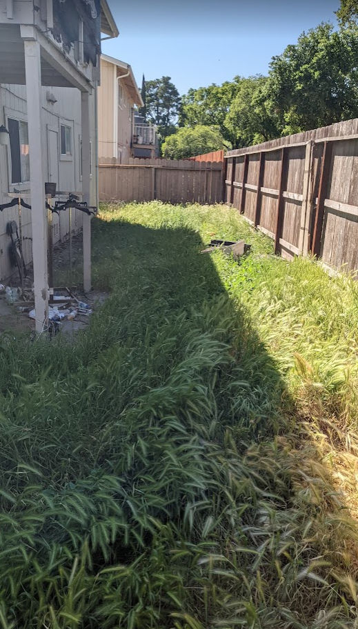
At one of my rental properties, I had some really ugly grass on the on both sides of the property and a jungle of weeds in the back. The space was wasted because not could or wanted to use it.
The previous owners (investors) didn’t want to / know how to maintain the property so I was able to buy it from them at a discount.
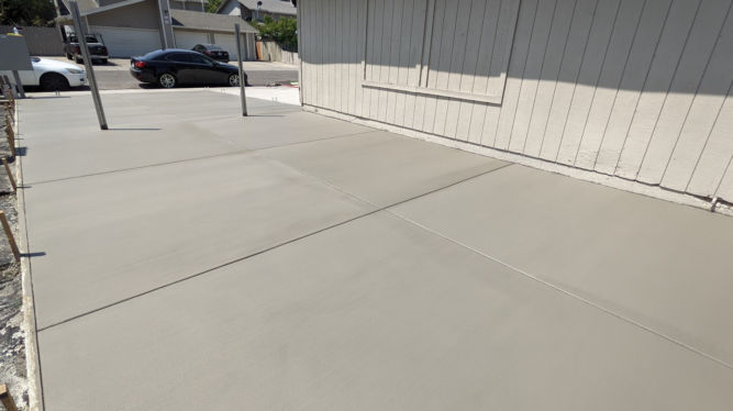
I decided to replace most of the grass (weeds) with concrete indicated in neon green below. I wanted the grass at the remaining areas indicated in dark green to be removed at a depth of 3 inches to place 3/4″ Ginger rock / Sonoma Gold rock. I also wanted to plant ten 15 gallon Italian Cypress trees along the eastern fence.
Here’s how the project went from start to finish.
Day 1: Hauling and Dumping Garbage
Loading debris into trailer using a wheelbarrowCutting old fence with a chainsawPreparing to cover the trailer before going to the dumpOn the way to the dumpAt the Lovelace dump in Manteca
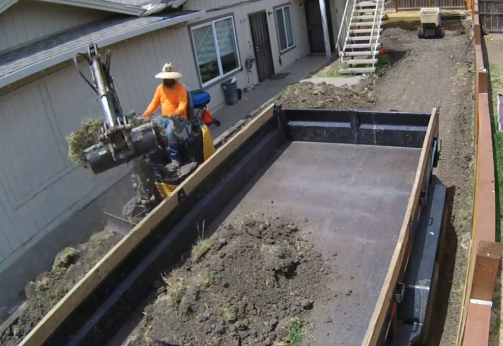
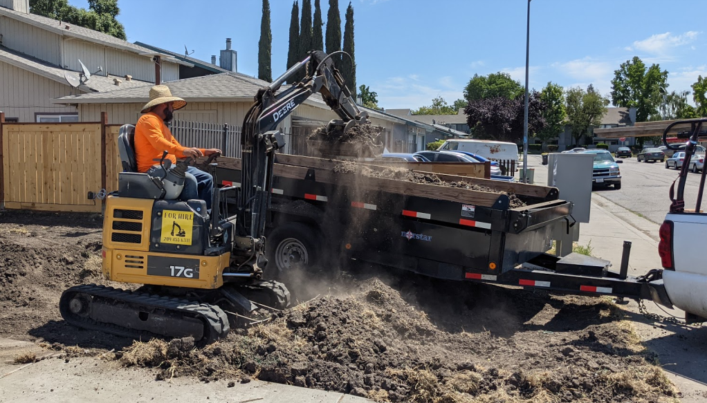
Day 2: Removing Grass and Dirt
Before removing grass and dirt Removing grass and dirt Removing grass and dirt Moving grass and dirt to trailer After removing grass and dirt Loading dirt in the back of the house into a power wheelbarrow Moving dirt from the back to the front Moving dirt from the back to the front Loading dirt into trailer Loading dirt into trailer Loading dirt into trailer
Day 3: Removing Grass, Dirt, and Old Concrete Slabs
Removing old concrete walkway Loading trailer with pieces of old concrete
Day 6: Compacting Gravel and Installing Rebar and Weed Fabric
Compacting the gravel The wood form in which the concrete will be poured Laying down rebar (not done yet) Added weed fabric under wood borders so that weeds won’t grow along perimeter of concrete slab
Day 7: Finishing Rebar Installation & Watering Yard
Installing rebar in the front yardInstalling rebar in the side yardWatering the yard
Let’s face it. Garages have been storage spaces rather than places to park your car. Here’s one approach to organizing your garage so that you can still fit your car in it.
1. Build a shelf
You can buy shelving, including heavy duty restaurant-grade ones with wheels which are expensive, or you can just follow the instructions at this YouTube video on how to make a simple set of shelves out of 2x4s.
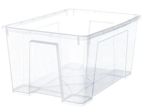
2. Buy transparent plastic containers
These clear boxes from IKEA are great. They’re also cheap. You don’t need to buy the lid.
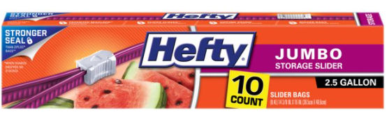
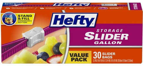
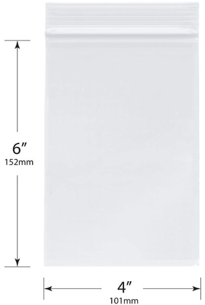
3. Buy zip loc slider bags
Slider bags are better because they are more secure. I use a few different sizes.
2.5 gallon1 gallon1 quart12″ x 12″ bag – 6 mil thickness
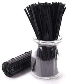
Twist ties are very useful for tying up cables. Available on Amazon.
5. Place related items together
For example, the picture below is of a bin labeled “Fasteners” which includes nails, screws, bolts, etc. Loose items are placed in appropriately-sized bags. Others are just placed directly in the bin unless their box or plastic container is mostly empty in which case I’d transfer the contents to a bag to not waste space.
In the photo below, the bin is label “Plumbing”. Not everything needs to be in a bag, like the PVC glue. Loose items or small parts that go together with larger parts are bagged so they don’t get lost.
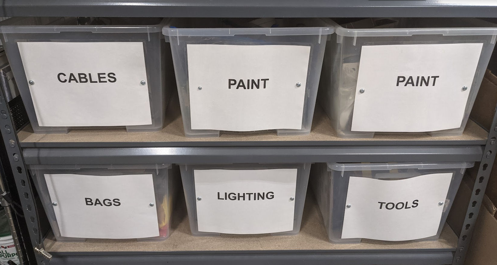
6. Label bins
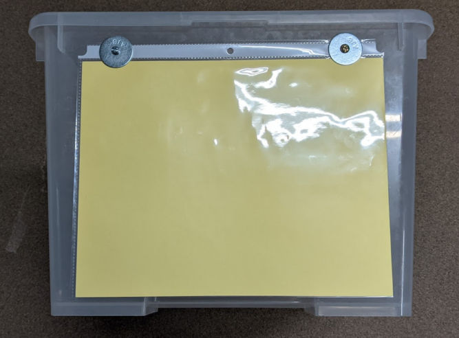
You can label bins using a label maker. I wanted larger labels so I printed category names on white paper, laminated it, and bolted it to the bins.
By now, your garage should feel a lot bigger and you won’t keep buying things you already have and you won’t spend forever looking for things.
UPDATE: July 29, 2021
Instead of laminating printed sheets of paper, I found a simpler, more flexible solution. Just buy clear sheet protectors for 3 ring binders. $5.00 on Amazon for thin ones. $20 on Amazon for thick, 5.5 mil vinyl ones (preferred). Just drill two holes in the plastic bins where the 2 outer sleeve holes are and fasten using a small bolt with a washer. Then, print your labels and insert them from the side.