


The free version of SketchUp offers many tools for drawing in 3D.
Following is a list of them and how to use them.
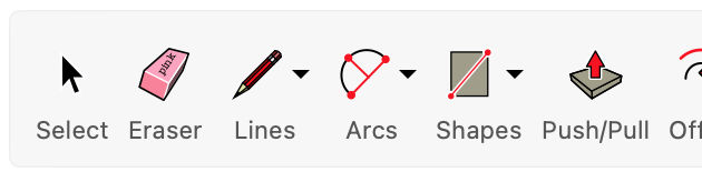
Select Tool

Select items and objects in the model.
Tool Operation
- Click on an item or object.
Modifier Keys
- Hold Ctrl = Add an item to the selection set.
- Hold Shift = Add and/or subtract an item to/from the selection set.
- Hold Shift+Ctrl = Subtract an item from a selection set.
Tips
- Double-click a face to select the face and all of its edges.
- Double-click an edge to select the edge and the faces that share it.
- Triple-click an edge or face to select all connected items.
- Double-click an object to edit it.
- Ctrl+A = Select all visible items in the model.
- Ctrl+T = Deselect all selected items in the model.
Lasso Tool
Make precise selections.
Tool Operation
- Click and drag to draw selection boundary.
Modifier Keys
- Hold Ctrl = Add an item to the selection set.
- Hold Shift = Add and/or subtract an item to/from the selection set.
- Hold Shift+Ctrl = Subtract an item from a selection set.
Tips
- Drag to the right to create a window selection that will capture items entirely within the selection boundary.
- Drag to the left to create a crossing selection that will capture anything the selection boundary touches.
- Make single-click selections just like the Select tool.
Eraser Tool
Erase entities.
Tool Operation
- Click on entity to erase. Alternatively, hold down mouse button drag over entities. All entities are erased when mouse button is released.
Modifier Keys
- Ctrl = Toggle soften and smooth edges.
- Alt = Toggle unsmooth edges and unhide edges and objects.
- Shift = Toggle hide edges and objects.
- Ctrl + Shift = Toggle deselect edges and objects selected by the eraser tool.
Paint Bucket Tool
Assign colors and materials to items and objects.
Tool Operation
- (Optional) Preselect the items or objects that you want to paint.
- Select a materials library using drop down list in Materials Browser.
- Select a material from materials library.
- Click on faces to paint.
Modifier Keys
- Alt = Sample material for painting.
- Shift = Toggle paint all faces with matching materials.
- Ctrl = Toggle paint all connected faces with matching materials.
- Shift + Ctrl = Toggle paint all faces on the same object with matching materials.
Line Tool
Draw edges or line entities.

Tool Operation
- Click to set the first point.
- Move cursor.
- Click to set the second point (creating an edge).
- (Optional) Move cursor.
- (Optional) Click to set a third point.
- (Optional) Repeat step 4-5 to create additional connected edges.
Modifier Keys
- Alt = Cycle through linear inference options (All On; All Off; Parallel/Perpendicular Only).
- Hold Shift = Lock Line tool to the current direction inference.
- Arrow keys = Lock Line tool to specific inference direction (→ = Red, ← = Green, ↑ = Blue, ↓ = Parallel/Perpendicular).
Tips
- Esc = Cancel operation.
- Once you’ve drawn a closed loop of at least 3 coplanar edges, a face will fill in automatically.
Freehand Tool
Create hand-drawn curve entities.
Tool Operation
- Click and drag to draw a freehand curve.
Modifier Keys
- Ctrl = Decrease the segments of the last drawn freehand curve.
- Alt = Increase the segments of the last drawn freehand curve.
- Before an operation, use arrow keys to lock the drawing plane of a curve (→ = Red, ← = Green, ↑ = Blue, ↓ = Parallel/Perpendicular).
Tips
- Segments may only be modified immediately after creating a curve.
Arc Tool
Draw Arc entities.
Tool Operation
- Click to set arc’s center. Optionally, click and drag first point to set drawing plane.
- Move cursor to define first arc point or enter radius.
- Click to set first arc point.
- Move cursor around the protractor guide or enter angle.
- Click to set second arc point.
Modifier Keys
- Hold Shift = Lock current inference direction.
- Arrow keys (before 1st click) = Lock protractor rotation axis direction (→ = Red, ← = Green, ↑ = Blue, ↓ = Parallel).
- Arrow keys (after 1st click) = Lock drawing direction to specific inference direction (→ = Red, ← = Green, ↑ = Blue, ↓ = Parallel/Perpendicular).
Tips
- Esc = Cancel operation.
- Click Window > Model Info > Units > Angle Units to change snapping angle.
- Ctrl '+' or Ctrl '-'= Change the number of segments.
2-Point Arc Tool
Draw 2-Point Arc entities.

Tool Operation
- Click to set start point of arc.
- Click at ending point of arc or enter value.
- Click to set bulge distance or enter value to finish arc.
Tool Operation (Tangent Inference locked)
- Click to set start point of arc at an existing edge or vertex.
- Click an end point for arc, or enter value.
Modifier Keys
- Alt = Lock tangent arc drawing.
- Hold Shift = Lock current inference direction.
- Arrow keys = Lock drawing direction to specific inference direction (→ = Red, ← = Green, ↑ = Blue, ↓ = Parallel/Perpendicular).
Tips
- Esc = Cancel operation.
- Ctrl '+' or Ctrl '-'= Change the number of segments.
- When multiple edges intersect, define tangency by hovering over one of the edges before starting the arc.
3-Point Arc Tool
Draw 3-Point Arc entities.
Tool Operation
- Click to set start point of arc.
- Click to set second point. The arc will always go through this point.
- Click to finish the arc, or enter an angle to define arc’s section of a circle.
Tool Operation (Tangent Inference locked)
- Click to set start point of arc at an existing edge or vertex.
- Click an end point for arc, or enter value.
Modifier Keys
- Alt = Lock tangent arc drawing.
- Hold Shift = Lock current inference direction.
- Arrow keys = Lock drawing direction to specific inference direction (→ = Red, ← = Green, ↑ = Blue, ↓ = Parallel/Perpendicular).
Tips
- Esc = Cancel operation.
- Ctrl '+' or Ctrl '-'= Change the number of segments.
- When multiple edges intersect, define tangency by hovering over one of the edges before starting the arc.
Pie Tool
Draw Pie entities.
Tool Operation
- Click to set pie’s center. Optionally, click and drag first point to set drawing plane.
- Move cursor to define first arc point or enter radius.
- Click to set first arc point.
- Move cursor around the protractor guide or enter angle.
- Click to set second arc point.
Modifier Keys
- Hold Shift = Lock current inference direction.
- Arrow keys (before 1st click) = Lock protractor rotation axis direction (→ = Red, ← = Green, ↑ = Blue, ↓ = Parallel).
- Arrow keys (after 1st click) = Lock drawing direction to specific inference direction (→ = Red, ← = Green, ↑ = Blue, ↓ = Parallel/Perpendicular).
Tips
- Esc = Cancel operation.
- Click Window > Model Info > Units > Angle Units to change snapping angle.
- Ctrl '+' or Ctrl '-'= Change the number of segments.
Rectangle Tool
Draw rectangular face entities.

Tool Operation
- Click to set first corner.
- Move cursor diagonally.
- Click to set second corner.
Modifier Keys
- Ctrl = Toggle drawing from center.
- Hold Shift = Lock Rectangle to current drawing plane inference.
- Arrow keys = Toggle lock drawing plane inference (→ = Red, ← = Green, ↑ = Blue, ↓ = Parallel).
Tips
- Esc = Cancel operation.
- When drawing rectangles, you can specify length & width by separating the measurements with a comma. For example: to draw a two foot by four foot rectangle, you can enter 2', 4' into the measurement box. The order of the measurements matches the order of the axes (R, G, B). For example: Red, then Green; Red, then Blue; or Green, then Blue.
Rotated Rectangle Tool
Draw rectangular face entities.
Tool Operation
- Click to set first corner. Optionally, click and drag first point to set drawing plane.
- Move your cursor around the protractor to set the direction of the first edge.
- Click to set second corner.
- Move your cursor to set the length and angle of the second edge.
- Click to set third and final corner.
Modifier Keys
- Hold Shift = Lock current inference direction.
- Alt (after 1st click) = Lock drawing plane for first edge.
- Alt (on a locked plane, after first click) = Set protractor baseline.
- Alt (after 2nd click) = Set protractor baseline.
- Arrow keys (before 1st click) = Lock protractor rotation axis direction (→ = Red, ← = Green, ↑ = Blue, ↓ = Parallel).
- Arrow keys (after 1st click) = Lock drawing direction to specific inference direction (→ = Red, ← = Green, ↑ = Blue, ↓ = Parallel/Perpendicular).
Tips
- Esc = Cancel operation.
Circle Tool
Draw Circle entities.
Tool Operation
- Click to set center point.
- Move cursor away from center point to define radius.
- Click to finish circle.
Modifier Keys
- Hold Shift = Lock current inference direction.
- Arrow keys (before 1st click) = Lock surface normal (→ = Red, ← = Green, ↑ = Blue, ↓ = Parallel).
- Arrow keys (after 1st click) = Lock drawing direction to specific inference direction (→ = Red, ← = Green, ↑ = Blue, ↓ = Parallel/Perpendicular).
Tips
- Esc = Cancel operation.
- Ctrl '+' or Ctrl '-'= Change the number of segments.
Polygon Tool
Draw Polygon entities.
Tool Operation
- Click to set center point.
- Move cursor away from center point to define radius.
- Click to finish polygon.
Modifier Keys
- Hold Shift = Lock current inference direction.
- Ctrl = Toggle between inscribed and circumscribed radii of polygon.
- Arrow keys (before 1st click) = Lock surface normal (→ = Red, ← = Green, ↑ = Blue, ↓ = Parallel).
- Arrow keys (after 1st click) = Lock drawing direction to specific inference direction (→ = Red, ← = Green, ↑ = Blue, ↓ = Parallel/Perpendicular).
Tips
- Esc = Cancel operation.
- Ctrl '+' or Ctrl '-'= Change the number of segments.
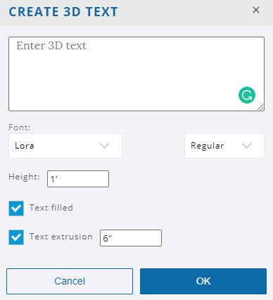
3D Text Tool
Push/Pull Tool
Push and pull face entities to add or subtract volume from your 3D models.
Tool Operation
- (Optional) Preselect the face that you want to push/pull.
- Click on a face to start push/pulling.
- Move cursor to push or pull face.
- Click to set face or enter distance.
Modifier Keys
- Ctrl = Toggle create new starting face.
- Alt = Toggle Stretch mode.
Tips
- Esc = Cancel operation and clear selection.
- When a face is pre-selected, you can click anywhere in the model to begin push/pulling it, and then click anywhere to set it down.
- Double-click to repeat a Push/Pull distance, in the same direction.
Follow Me Tool
Extrude a face along a path.
Tool Operation (Nothing Pre-selected)
- Click the face of the profile that you want to extrude.
- Move cursor along the edge or edges that you want the profile to follow.
- Click to set the extrusion.
Tool Operation (Preselect Path)
- Use the Select tool to pre-select a continuous set of edges to define the path.
- (Alternatively) Pre-select a face to define the perimeter of the face as the path.
- Activate the Follow Me tool.
- Click the face of the profile that you want to extrude.
Modifier Keys
- Alt = Use perimeter of face as the path.
Tips
- Esc = Cancel operation.
Offset Tool
Create copies of lines at a uniform distance from originals.
Tool Operation
- Click on a face.
- Move cursor.
- Click to finish offset operation.
Modifier Keys
- Alt = Toggle allow/trim overlap.
Tips
- Esc = Cancel operation.
Outer Shell Tool
Combine all selected solid objects into a single solid object and remove interior items.
Tool Operation
- Select first solid object.
- Select second solid object.
- Select next solid object or press Esc to complete.
Move Tool
Move or copy entities, and/or rotate objects.
Tool Operation
- Click on an entity or object to pick it up.
- Move cursor to move entity or object to a new location.
- Click to set it down or enter a distance.
Modifier Keys
- Ctrl = Cycle Move/Copy/Stamp.
- Alt = Toggle Autofold mode (useful for overriding Move tool constraints); when hovered over an object, use Alt to cycle through grip types.
- Shift = Lock Move to the current inference direction.
- Arrow keys = Toggle lock inference direction (→ = Red, ← = Green, ↑ = Blue, ↓ = Parallel/Perpendicular).
Tips
- Esc = Cancel operation.
- When items are pre-selected, you can click anywhere in the model to begin moving them, and then click anywhere to set them down. This is an effective way to move things precisely and/or align things to other things.
- Click the red crosshairs that appear on the bounding box of an object to rotate that object.
- After moving a copy, you can type a number followed by the X key and then press Enter to create an array of copies.
Rotate Tool
Rotate, stretch, distort, or copy items or objects along a rounded path.
Tool Operation
- (Optional) Preselect the items or objects you want to rotate.
- Click on an item or object to both make a selection and set the center point of rotation.
- Move cursor to indicate start point of rotation.
- Click to set starting point of rotation.
- Move cursor to indicate end point of rotation.
- Click to complete rotation, or enter angle in degrees.
Modifier Keys
- Ctrl = Toggle rotate a copy.
- Before first click, hold Shift to lock protractor inference.
- Before first click, use arrow keys to toggle the protractor inference lock direction (→ = Red, ← = Green, ↑ = Blue, ↓ = Parallel).
- After first click, use arrow keys to toggle rotation inference lock direction (→ = Red, ← = Green, ↑ = Blue, ↓ = Parallel/Perpendicular).
Tips
- Esc = Cancel operation.
- During Step #2 of the tool operation steps above, you can click-drag the protractor along an edge or axis to set an axis of rotation.
- After rotating a copy, you can type a number followed by the letter X and then press Enter to create a rotated array of copies.
- When inputting rotation values into the Measurements box, you can enter either an angle of rotation, in degrees (for example 45 Enter),or a slope expressed as a rise:run architectural slope notation (for example 4:12 Enter).
Scale Tool
Resize or stretch items and objects.
Tool Operation
- (Optional) Preselect the items or objects you want to scale.
- Click on a face or object.
- Click on a Scale grip.
- Move cursor to resize or stretch item or object.
- Click to finish scaling item or object.
Modifier Keys
- Ctrl = Toggle scale about center.
- Shift = Toggle uniform scale.
Tips
- Esc = Cancel operation.
- Click a corner grip for 3-way scale. Default = Uniform. Pressing Shift = Non-uniform.
- Click a midline grip for 2-way scale. Default = Non-uniform. Pressing Shift = Uniform.
- Click a center grip for 1-way scale. Default = Non-uniform. Pressing Shift = Uniform.
- When scaling an item or object you have the option to enter either a scale factor (for example 2.5 Enter will make the things you’re scaling 250%, or two and a half times bigger), or you can simply input the size that you want the thing you’re scaling to be (for example, if scaling up along the blue axis direction, 6' Enter will make the selection six feet tall).
Tape Measure Tool
Measure distances, create guide lines, or scale a model.
Tool Operation
- Click at starting point of measurement.
- Move cursor.
- Click at ending point of measurement.
Modifier Keys
- Ctrl = Toggle create guide lines.
- Hold Shift = Lock Tape Measure to current inference direction.
- Arrow keys = Lock Tape Measure to specific inference direction (→ = Red, ← = Green, ↑ = Blue, ↓ = Parallel/Perpendicular).
Tips
- Esc = Cancel operation.
- After measuring from point to point, you can input a distance to scale/resize the model.
- When in Create Guide mode, begin on an edge to create a guide of infinite length; begin on a point to create a guide of finite length.
Dimension Tool
Place Dimension entities.
Tool Operation
- Click at starting point of dimension.
- Move cursor.
- Click at ending point of dimension.
- Move cursor to pull out the dimension string.
- Click to set the dimension string.
Tips
- Esc = Cancel operation.
Text Tool
Create Text entities.
Tool Operation
- Click on an entity to indicate ending point of leader line (location where leader will point).
- Move cursor to position text.
- Click to place text.
- (Optional) Click in text box.
- (Optional) Enter text in text box.
- Click outside text box to complete operation.
Tips
- Esc = Cancel operation.
Section Plane Tool
Create section cuts through your model or objects.
Tool Operation
- Click on a face to create a section plane that is aligned to that face.
Modifier Keys
- Hold Shift (before 1st click) = Lock section plane to current orientation.
- Arrow keys = Toggle lock section plane orientation (→ = Red, ← = Green, ↑ = Blue, ↓ = Parallel).
Tips
- It’s possible to activate multiple section planes at the same time, as long as the section planes are in different contexts. For example, you can activate one section plane through the model, and then activate another section plane through a group or component object and have both planes active at the same time.
Protractor Tool
Measure angles and create angled guide line entities.
Tool Operation
- Place protractor’s center at vertex of angle.
- Click to set vertex. (Alternatively: click and drag first point to set rotation plane.)
- Move cursor in circle until touching start of angle.
- Click to set start of angle.
- Move cursor in circle until touching end of angle.
- Click to measure angle.
Modifier Keys
- Ctrl = Toggle create guide lines.
- Before first click, hold Shift to lock protractor inference.
- Before first click, use arrow keys to toggle the protractor inference lock direction (→ = Red, ← = Green, ↑ = Blue, ↓ = Parallel).
- After first click, use arrow keys to toggle rotation inference lock direction (→ = Red, ← = Green, ↑ = Blue, ↓ = Parallel/Perpendicular).
Tips
- Esc = Cancel operation.
- When inputting rotation values into the Measurements box, you can enter either an angle of rotation, in degrees (for example 45 Enter ), or a slope expressed as a rise:run architectural slope notation (for example 4:12 Enter).
Axes Tool
Move or reorient drawing axes.
Tool Operation
- Click to set axis origin.
- Move cursor to locate direction for the red axis.
- Click to set the red axis.
- Move cursor to locate direction for the green axis.
- Click to set the green axis.
Modifier Keys
- Alt = Alternate axis orientation (after clicking to set the origin).
Tips
- Esc = Cancel operation.
Tag Tool
Apply tags to objects.

Tool Operation
- Select a single tag in the Tags panel.
- Click on an item or object to assign the selected tag.
Modifier Keys
- Alt = Sample the assigned tag from an object or item.
- Ctrl = Apply a tag to all instances of a component.
- Shift = Replace the current tag of all items in a given context with the selected tag.
Tips
- Before tagging edges and faces, consider creating groups or components, and then tag the group or component instead.
- Use ‘Select > All with Tag’ in the right-click context menu to select all items in a given context that share the same tag.
- Color by Tag can be a useful way to identify which tags have been assigned to which items.
Walk Tool
Walk through (tour) a model.
Tool Operation
- Click and drag the cursor: Up = Walk forward; Down = Walk backward; Left = Turn left; Right = Turn right.
Modifier Keys
- Hold Shift = Float up instead of forward, or down instead of backward.
- Hold Ctrl = Run instead of walk.
- Hold Alt = Walk through things.
Tips
- Esc = Cancel operation.
- The further you drag the cursor away from the start point (indicated by crosshairs), the faster you’ll walk.
Position Camera Tool
Position camera at a specific eye height.
Tool Operation
- Click anywhere in the model to place the camera. The camera will be positioned above the point where you click, at the eye height distance specified in the measurements box.
- (Optional) Click and drag from one point in the model to another point in the model to create a target camera. The point you drag from will be the exact location where the camera will be positioned, the point you drag to will establish the camera target.
Look Around Tool
Pivot camera from a stationary point.
Tool Operation
- Click and drag the cursor to pivot the camera (i.e. look around in the model).
Tips
- Esc = Enable previously selected tool.
Orbit Tool
Orbit camera around model.
Tool Operation
- Click and drag cursor within the drawing area to orbit the camera.
Modifier Keys
- Hold Shift = Pan tool.
- Hold Ctrl = Suspend gravity (do not try to keep vertical edges up and down).
Tips
- Esc = Enable previously selected tool.
Pan Tool
Move camera vertically or horizontally.
Tool Operation
- Click and drag cursor within the drawing area to pan the camera.
Tips
- Esc = Enable previously selected tool.
Zoom Tool
Move camera in or out.
Tool Operation
- Click and drag cursor within the drawing area to zoom the camera.
Modifier Keys
- Hold Shift = Change field of view degrees.
Tips
- Esc = Enable previously selected tool.
Zoom Window Tool
Zoom in to a specific area of the model.
Tool Operation
- Click and drag the cursor across the items in the model that you want to zoom into.
Tips
- Esc = Enable previously selected tool.